Sponsored by MKS NewportReviewed by Olivia FrostJul 14 2026
As photonic products become more advanced and compact, precision optical alignment during assembly and assessment grows increasingly crucial.
Image Credit: Pete Hansen/Shutterstock.com
This is like how metrology becomes progressively more demanding in IC manufacturing as circuit dimensions shrink and alignment tolerances tighten to support more miniaturized, sophisticated packaging techniques
For photonic devices, optical coupling misalignments during assembly and assessment can adversely affect system performance and dependability. It is not uncommon for these alignment tolerances to be in the micron or submicron range, owing to the small dimensions of the fibers involved.
This article investigates the motion technologies that allow producers to satisfy these stringent alignment specifications using two of the most valuable classes of current photonic products as examples: photonic integrated circuits (PICs) and display systems for augmented and virtual reality (AR/ VR) headsets.
The requirements of these applications will be detailed, along with the types of motion systems and their associated software algorithms. It will also outline specific Newport motion and positioning solutions most applicable to these tasks.
PICs
Photonic integrated circuits (PICs) are at the cornerstone of numerous sophisticated optical systems, such as telecommunications, data centers, and sensors. Just as a conventional silicon semiconductor wafer combines multiple individual electronic parts onto a single substrate, PICs integrate multiple photonic parts onto a single substrate.
Using photonic rather than electronic components offers substantial advantages in speed, energy efficiency, and data capacity over conventional microelectronic components.
In the same way that ICs are interconnected electrically with wires or conductive traces, PICs commonly interface with other devices via optical fibers or waveguides. Moreover, just as the optimal electrical interconnection has low resistance, the ideal fiber-to-PIC connection should have the lowest possible optical loss (i.e., the highest transmission).
There are several points in the PIC manufacturing process that require optical alignment. These include:
Wafer-Level Assessment
This consists of assessing photonic components directly on the optical wafer prior to dicing and packaging. Assessment at this point enables early-stage detection of manufacturing defects and maximizes yields.
Typical assessments include measuring insertion and reflection losses, verifying device functionality (ensuring proper operation of devices such as modulators, switches, or multiplexers), optical resonator characterization, and dispersion and bandwidth measurements.
Fiber Alignment
This process involves precise positioning of input/output optical fibers relative to the photonic components during assembly, ensuring optimal light transfer and minimizing signal loss in the final product.
While this can be carried out by passively employing PIC structures to align the optical fibers, the best outcomes are achieved through active alignment. In this case, the fiber position is adjusted while the optical signal is monitored in real time.
Alignment between a single fiber and another optical channel has been conducted for multiple years, but the task becomes more complicated and advanced for PICs. Several are frequently held in a jig precisely aligned to each other.
Once the first fiber has been aligned to its source, the set is adjusted to maximize the signal on the last fiber while maintaining the alignment of the first fiber. After determining the proper alignment, UV-cure epoxy is applied, and the fiber set is permanently bonded to the PIC.
Grating Coupling Assessment
Gratings are occasionally used to couple light in and out of photonic devices. These assessments measure the coupling performance between a grating and an optical fiber.
Optical Transceiver Assessment
In addition to insertion loss and coupling efficiency, transceiver assessment may involve optical spectrum evaluation, attenuation, total output power measurement, and dispersion. It also requires characterization of performance parameters such as bit error rate (BER), jitter, and signal fidelity.
Assembly and Packaging
During this stage, PICs may be interconnected with one another and with various components, such as lasers and detectors.
AR/VR Headsets and AR/VR glasses
To create immersive experiences for users, AR/VR headsets pair high-resolution (typically stereoscopic) visuals with high-fidelity audio. The typical AR/VR device integrates several individual photonic parts, including microdisplays, waveguides, couplers and combiners, and sensors (which may integrate their own illumination).
For this reason, accurate alignment of these elements relative to one another is necessary to achieve maximum image quality, optimize the field of view, and enhance brightness. For the sensors, the objective is to achieve the highest precision and longest range while minimizing latency in motion tracking.
Since AR/VR systems are composed of numerous separate parts, a significant number of alignment tasks are carried out during their assembly and assessment. These include:
Optical Axis Alignment
Certain AR headsets depend on a beamsplitter to introduce an image projected from a microdisplay into the user’s line of sight, combining the display with the user’s direct view of the real world. In this case, all free-space optics in the system must be aligned to a common optical axis. This process may involve multiple individual components, including relay/projection optics and the beamsplitter.
Display-to-Waveguide Alignment
More sophisticated AR/VR systems use waveguides rather than beamsplitters to channel light from the display to the user’s eyes. Aligning the display source with this highly miniaturized waveguide is crucial, as it typically requires tight tolerances, so any errors can degrade image quality. These might include blurring, color misregistration, or uneven brightness across the field of view.
Binocular Alignment
A critical assembly task is positioning each display system so it aligns with the anticipated position of the wearer’s optical axis (defined as a line passing through the center of the eye lens and the fovea).
This alignment must be consistent with regard to position and angular orientation. In addition, maintaining a specific separation between the optical axes of the two displays (inter-pupillary distance) may be necessary.
In both displays, the focus, field of view, and magnification must also be closely aligned so users can comfortably fuse the individual left and right images into a single apparent image. Adjusting these parameters may require positioning different components or groups of components.
Eye-Tracking System Alignment
VR systems employ eye-tracking more frequently than AR systems. In this case, the sensors that track user eye movement must align with the display and the lenses to ensure precise detection.
External Sensor Alignment
AR/VR headsets are frequently equipped with cameras or sensors that track user movement and the surrounding environment, enabling features such as head tracking, gesture recognition, or real-world environment mapping. The alignment involves positioning the lenses relative to the cameras or sensors so the sensor captures the image or data in the appropriate focal plane.
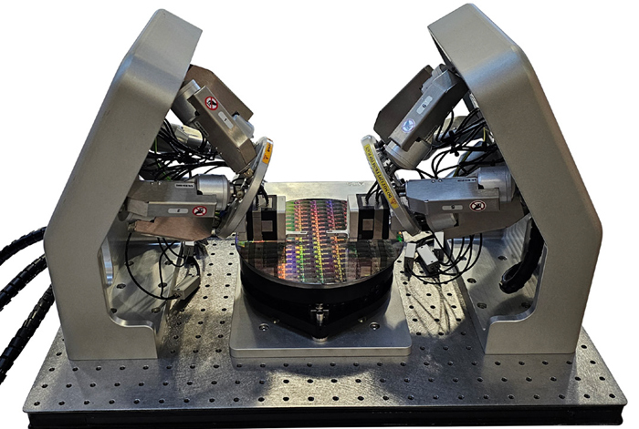
Image Credit: MKS Newport
Production Assessment Requirements
While the aforementioned alignment tasks are diverse, they still share numerous common requirements regarding both functionality and accuracy. For PIC assembly procedures, alignment tolerances for linear position are typically in the micron or submicron range, and angular alignment tolerances range from ±0.1 to ±10 μrad.
In AR/VR headsets, display-to-waveguide alignment tolerances exhibit similar values. Most other alignment tasks in AR/VR headsets are more forgiving than this; angular alignment tolerances for some of these can exceed one mrad.
Another requirement in both applications is the almost universal demand for high throughput. Tasks such as fiber alignment must be completed rapidly and repeatably, as producers seek to maximize throughput without compromising quality to achieve competitive prices.
Achieving alignment with both the necessary speed and precision requires motion hardware with high precision, while also relying on advanced software and algorithms engineered to optimize the procedure.
Whether assessing PICs at the wafer level or aligning displays in AR/ VR systems, the challenge is to rapidly and accurately achieve “first light” (the detection point for an optical signal) and subsequently fine-tune the alignment for optimal performance.
This process requires an integrated approach that combines sophisticated motion control systems with intelligent algorithms that can manage the complexity of positioning micro-scale components in three to six degrees of freedom.
The first step in both PIC and AR/VR applications is to locate the initial signal, a task frequently carried out via algorithms such as raster scanning or spiral searching. These algorithms define a search pattern that incrementally moves the components until a signal is detected. After the first light is found, the alignment process shifts to optimization.
At this point, more refined methods, including centroid or hill-climbing algorithms, are employed to adjust the positioning with submicron accuracy. This optimization reduces signal loss and ensures maximum performance in data transmission for PICs or image clarity and tracking precision for AR/VR headsets.
Motion control systems are critical for enabling these alignment procedures. For PIC assessment, positioning systems frequently need to support several degrees of freedom, including both linear and rotational axes.
The ability to control movement with submicron accuracy while maintaining stability is critical, as even minor deviations can result in substantial optical losses. Systems must also be able to operate at high speeds to satisfy manufacturing needs, particularly in wafer-level assessment environments where throughput is essential.
In AR/VR applications, optical component alignment, including microdisplays and waveguides, typically involves fewer degrees of freedom while still requiring high accuracy, as any misalignment can distort the user experience. In this case, linear motion systems are frequently sufficient; however, they must still provide precise control to guarantee optimal image quality.
Speed and accuracy are always in balance throughout the alignment process. Quicker movement can shorten overall assessment or assembly times, but without meticulous control, it risks losing the fine precision necessary for effective coupling or image alignment.
Motion systems must deliver both: rapid movement for coarse adjustments and ultra-precise control for fine-tuning. The integration of feedback systems, which provide real-time monitoring of the optical signal, facilitates continuous adjustment, ensuring that the alignment process is both fast and dependable.
Overview of Newport Motion and Positioning Solutions
Newport provides a wide variety of motion control and positioning solutions that can deliver the combination of speed, precision, and stability needed for affordable manufacturing assessment and assembly tasks. By pairing state-of-the-art hardware with sophisticated software, Newport delivers flexible solutions that can adapt to the unique needs of each application.
Given that these diverse components can be combined in a practically limitless number of ways, the system designer’s product selection task can appear overwhelming. The following examples present some typical combinations for the most common applications, offering some guidance on where to start when specifying a motion control system.
Photonic Integrated Circuits
Wafer/Die Positioning
- Two crossed IDL linear motion stages are combined with a ZVR-integrated vertical and rotation stage. This enables xy positioning over a large area, and high-resolution z motion and rotation.
- Components included: X – IDL225-400LM; Y - IDL225-400LM; Z-Theta – ZVR-PC
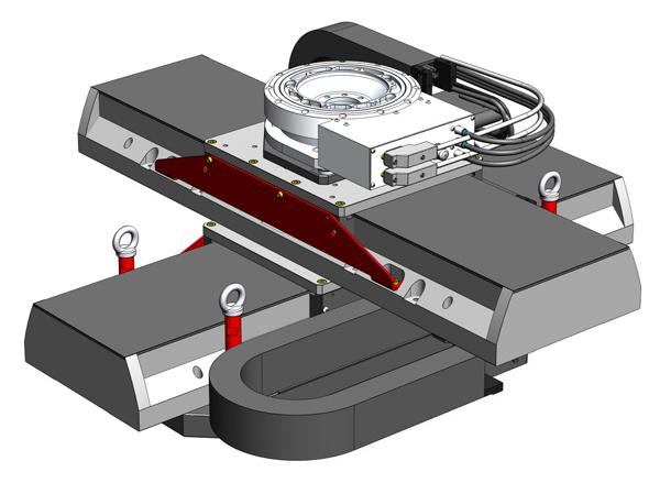
Image Credit: MKS Newport
Silicon Photonics Testing
- Hexapod: HXP50-MECA
- Nanopositioner: NPXY100SG-D
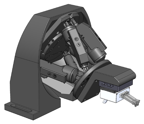
Image Credit: MKS Newport
Optical/Electrical Probing
- X: M-VP-25XL
- Y: M-VP-25XL
- Z: M-VP-5ZA
- ThetaX: M-RS65 with TRA12CC
- ThetaY: M-GON40-U with TRA12CC
- ThetaZ: M-GON40-L with SM-13
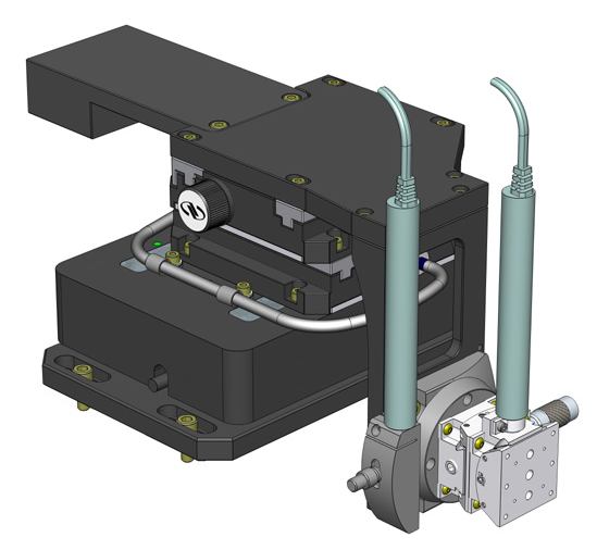
Image Credit: MKS Newport
Communication Module Optical Alignment/Assembly
- X: XML210-S
- Y: XMS100-S
- Z: XMS50V with pneumatic counterbalance
- ThetaX: BGS50CC
- ThetaY: URS100BCC
- ThetaZ: BGS80CC
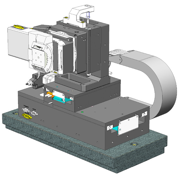
Image Credit: MKS Newport
AR/VR/MR Tools
Waveguide Image Quality Testing
- HXP200 mounted on top of IDL280-600LM
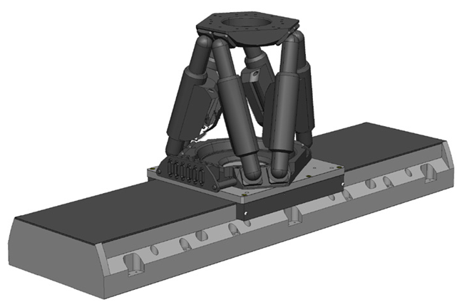
Image Credit: MKS Newport
Head-Mounted Display Performance Testing
- Yaw: RGV160BL-S
- Pitch: RGV100HL-S
- Roll: RGV100HL-S
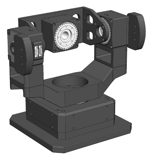
Image Credit: MKS Newport
Software
The aforementioned hardware represents only part of the solution offered by Newport. The company’s XPS motion controllers feature advanced processors that incorporate preprogrammed optical alignment algorithms.
These photonic device search algorithms (PDSAs) enable optimization of different alignment tasks under various conditions and can be used individually or in combination.
As an example, certain search algorithms are optimal for finding the first light (the periphery of a light beam), after which other algorithms can reach the peak-power location with greater speed and precision.
Choosing the second algorithm may depend on whether the beam exhibits a Gaussian distribution or a top hat profile with multiple peaks. Some algorithms are capable of profiling both beam types and can also be employed in parallel.
The chart summarizes these integrated PDSAs and highlights the tasks for which they are beneficial.
Source: MKS Newport
| PSDA |
Beam Profile:
Gaussian or
Single Peak |
Beam Profile:
Plateau or
Multiple Peaks |
Find
First
Light |
Find Peak
Power |
Find Peak Power
along Beam
Axis (Z) |
Stop when Threshold
Reached |
Max Number
of Axes |
| Axis by Axis |
• |
|
|
• |
|
|
6 |
| Dichotomy |
• |
|
|
• |
|
|
6 |
Escalade
(Continuous) |
|
|
|
• |
• |
|
3 |
Escalade
(Square) |
|
|
|
• |
• |
• |
3 |
| Raster |
|
• |
• |
• |
|
• |
2 |
Spiral
(Continuous) |
|
• |
• |
• |
|
|
2 |
Spiral
(Square) |
|
|
• |
• |
|
• |
2 |
The XPS uses an Ethernet communications link and a website as a graphical user interface (GUI), providing access to all its integrated software instruments. This makes the XPS controller independent of the user’s operating system. In fact, any networked device running any operating system can access the controller via the internet.
This enables remote control of the system, code development, file transfer, or diagnostics to be conducted from any location. The different alignment algorithms described above are available as application programming interface (API) functions that can be invoked via simple text commands.
This software integration is a critical differentiator in Newport motion control systems. The company’s software controls the hardware while also delivering instantaneous visualizations and data acquisition instruments.
These capabilities support the tracking and optimization of the alignment process. By leveraging features such as graphical interfaces and customizable algorithms, the software simplifies real-time configuration, monitoring, and alignment adjustments.
All this facilitates bringing a process online, maintaining its functionality in volume manufacturing, and acquiring all the data necessary for meeting traceability and compliance guidelines.
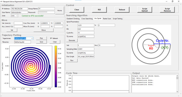
Image Credit: MKS Newport
Conclusion
Precision alignment is the foundation of success in both PIC and AR/VR headset assessment and assembly.
As these technologies evolve, the need for speed and accuracy in the alignment process becomes increasingly crucial. Newport continues to lead this evolution, providing cutting-edge solutions that enable the next generation of high-performance photonic products.

This information has been sourced, reviewed, and adapted from materials provided by MKS Newport.
For more information on this source, please visit MKS Newport.