Sponsored by MKS NewportReviewed by Olivia FrostJul 9 2026
Most optical networks have multiple fiber couplings, so even minor losses at these junctions can cause substantial signal degradation, jeopardizing data transmission. Accurate fiber alignment at the optical couplings in a network is, therefore, a prerequisite for precise and dependable optical data transmission, as it generates the lowest signal loss prior to optical system assembly or packaging.

Image Credit: Sashkin/Shutterstock.com
In addition, minimizing signal loss lowers optical power requirements, which in turn results in fewer repeaters, reduced capital expenses, and a lower incidence of failure.
Alignment Parameters and Procedures
Effective fiber alignment requires accurate adjustment of a precision motion control device along with an appropriate search algorithm optimized for use in the alignment application.
Figure 1 depicts a typical search operation together with the positional parameters related to optical fiber alignment. In the search process, the intensity of a well-characterized optical input beam (the laser diode shown in Figure 1) is compared to the output signal of the optical fiber under alignment.
Positional/Rotational Parameters
Motion controllers operate through a coordinate system in which an object has six degrees of freedom: three linear position parameters along the X, Y, and Z axes in a Cartesian coordinate system and three rotational parameters around those axes (see Figure 1(b)).
Every movement is defined in terms of translations along and/or rotations around the Cartesian axes. The fiber position is advanced through a raster scan to identify first light: the moment the laser beam first enters the optical fiber (Figure 1(a)).
Following detection of first light, the fiber's lateral, longitudinal, and angular coordinates undergo incremental adjustments to maximize the intensity of the optical signal output from the fiber.
In the simplest case, only lateral (X, Y) adjustments are required, whereas in multi-channel cases, all six degrees of freedom (X, Y, Z, x,y, and z) may need to be adjusted (Figure 1(b)).
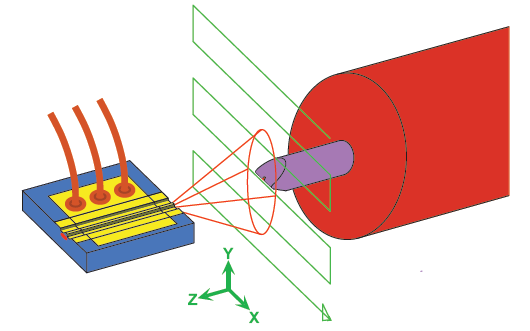
Figure 1. The operations and positional parameters of optical fiber alignment: (a) scan operations; (b) positional parameters for the optical fiber alignment. Image Credit: MKS Newport
Motion Control Parameters
Linear or rotary motion stages generate the controlled motions and trajectories used to move objects during optical fiber alignment. The following parameters are important to consider when choosing a motion system for optical fiber alignment:
- Minimum incremental motion (MIM) is the smallest increment of motion that can be consistently and reliably delivered by a device. Unlike resolution, which is a theoretical capability rather than a practical parameter, MIM represents the actual physical performance of the motion controller.
MIM can range from 100 to 1 nm; smaller MIMs come at a substantial cost in terms of alignment speed and beam-power increments. MKS Instruments’ XMS linear stages can achieve one nm MIM and 300 mm/second speed.
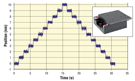
Figure 2. 1 nm MIM of an XMS linear stage: Insert – MKS Instruments’ XMS50-S Linear Motor Stage. Image Credit: MKS Newport
Repeatability refers to the ability to repeatably position an object. It can be unidirectional (always approaching the target position from the same direction) or bidirectional (approaching the target position from either direction).
This parameter is valuable for rapidly determining the peak power location of similar device designs. The XMS stage illustrated in Figure 2 exhibits 80 nm bidirectional repeatability.
- Position stability represents the capacity to maintain a position within specified tolerances over a given time interval. Composed of the sum of drift and vibrations, this measurement generally ranges from 0.5 to several microns. The alignment of fibers for assembly processes, such as bonding, depends on the positional stability of the motion system.
Figure 3 illustrates the positional stability of an MKS Instruments linear motion stage 250 ms after movement. Following settling, the stage exhibits less than 20 nm of positional variation.
- Additional motion parameters include: axis alignment, gimbal point location, system stiffness, pitch/ yaw, thermal considerations, fixture design, and Abbe error.
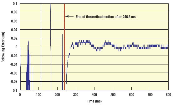
Figure 3. Step and settle characteristics of an MKS linear motion stage, 250 ms after being moved. Image Credit: MKS Newport
Representative Search Algorithms
- Successful optical fiber alignment requires the use of a positional search algorithm suitable for both the application and the phase in the alignment process. Search algorithms can be divided into two categories: 1) those most effective for detecting the first light, and 2) faster, more accurate algorithms for maximum power location.
First Light Searches
First light searches use two main strategies: raster scans and spiral scans. Raster scans are the simplest search technique, scanning a defined distance along one axis, indexing the position by a defined distance along another axis, and then repeating the cycle. Raster scans, depicted in Figure 1, are among the fastest techniques for locating the first light of the beam.
Spiral scans provide an additional method for first light searches. This technique searches the general beam area by using a spiral motion produced by synchronizing controlled motion in the X and Y axes.
Peak Power Searches
Following the identification of the first light, alternative search algorithms to raster or spiral scans are more suitable for locating the peak power location. The choice of peak power search algorithm depends on whether the beam exhibits a Gaussian distribution or a top-hat profile with multiple peaks.
The following examples are representative of the numerous alternative techniques.
- Hill climb is a straightforward two-dimensional search for the highest power. It works best for beams exhibiting a Gaussian profile and in cases where the optical power rises quickly. The hill climb technique, on its own, is not effective for identifying peak power with flat-beam profiles.
- Centroid search advances along one axis, identifies a peak, and then travels along a second axis to locate the last peak. Centroid searches are advantageous for top-hat or multi-peak profiles.
- Dichotomy search examines one axis at a time in large increments until a peak is located. A subsequent search cycle is carried out within this peak with finer steps to determine the peak maximum.
Motion Control Systems
Motion control systems used in fiber alignment range from simple manual stages for small-scale and R&D applications to fully automated manufacturing systems with high-accuracy motorized stages, pick-and-place automation, dispensing and curing systems, machine vision, and more. The following examples represent the manual and motorized motion control systems used in fiber alignment operations:
- Manual stages are the simplest and the least expensive motion control systems for accurate linear or rotational motion. They are employed in R&D and low-volume manufacturing settings. Figure 4(a) depicts an MKS ULTRAlign™ 562 manual stage that has been motorized by adding TRA actuators.
- Driven by piezoelectric actuators, piezoelectric stages (Figure 4(b)) are compact, four- to six-axis alignment systems. They enable high-resolution (<30 nm) adjustment for various combinations of X, Y, Z, θx, θy, and θz and can maintain their position without applied power.
- Linear motor stages with direct read encoders are the highest precision standard stages. When operated alongside precision motion controllers, these systems have 1 nm MIM capacity. MKS Instruments’ XMS linear motor stage, shown in Figure 4(c), can swiftly and easily navigate a 10 μm diameter region of a beam region exhibiting the highest power.
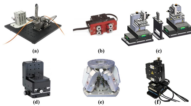
Figure 4. Manual and motorized motion stages: (a) Single fiber, single-end configuration with MKS 562 manual stages and CONEX-TRA actuators; (b) MKS 8071 4-axis aligner driven by Picomotor™ piezo actuators; (c) Double-sided configuration with MKS VP-25 and XMS stages; (d) MKS VP-25XA-XYZL integrated specifically for fiber alignment; (e) MKS HXP50 hexapod with horizontal and vertical beam paths; (f) MKS MLT-25XYZL/R integrated direct drive stages designed for fiber alignment. Image Credit: MKS Newport
- Designed as compact stages, XYZ assemblies featuring ball screw drives come with either a 100 nm or 10 nm MIM and are available in left and right versions for single or double-ended configurations. The 100 nm VP-25XA-XYZ from MKS Instruments is depicted in Figure 4(d).
- XYZ assembly with direct drive motor, delivering 5 nm MIM, with left- and right-handed configurations available.
- Hexapods are mechanical devices that employ six actuators operating entirely in parallel. These devices deliver a six-axis range of motion in a Cartesian coordinate system.
More compact than stacked stage systems, they are capable of complex combinations of linear and angular motions beneficial for critical rotation adjustments. MKS Instruments’ HXP50 hexapod is depicted in Figure 4(e).
These hexapods integrate advanced innovations that provide advantages in fiber alignment applications.
- MKS Instruments’ hexapods employ work and tool coordinate systems. Shown in Figure 5(a), these programmable coordinate systems permit independent manipulation of either the work (sample or device) or tool (cutter or beam). By employing this system, users can easily send positioning commands in the Cartesian coordinate system.
- Hexapods can encounter challenges during scanning operations that require a specific linear, rotational, or arc path to follow. Figure 5(b) demonstrates the motion of a standard hexapod when commanded to travel from one point to another in the X-axis (blue line).
The deviation from a straight line in the path can be as much as one millimeter. To reduce the run-out to just a couple of microns, MKS Instruments’ hexapods use RightPath Trajectory Control, allowing the device to follow specified linear, rotational, or arc trajectories with greater precision.
- HexaViz simulation: HexaViz is a free, downloadable simulation software that enables simulation of loads, motions, and potential collisions for all MKS HXP hexapods.
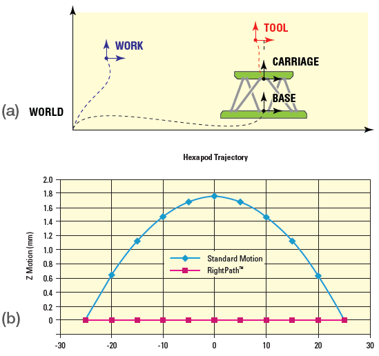
Figure 5. (a). MKS Instruments’ HXP hexapod Work and Tool coordinate systems transformation of axes; (b) RightPath™ trajectory showing runout. Image Credit: MKS Newport
Additional Fiber Alignment System Components
A full fiber alignment system is composed of the receiver or transmitter device, the device fixture or holder, a light source, a motion control system, and ancillary parts. These latter elements, with several described in Table 1, include:
- Detectors that calculate beam power: Paired with a power meter, they track the optical signal to identify the highest transmitted power. Additionally, a beam profiler may be required to characterize the beam shape.
- Power meters: Coupled with detectors for the specific wavelength and measured power range, and a minimum data transfer rate of 2 kHz, they ensure rapid alignment and productivity.
- Vision systems identify device proximity and the rough alignment of fiber ends. A vision system permits an extremely small gap, keeping the fiber ends nearly touching to maximize the transmitted power.
- Dispensing/bonding systems that dispense a precise volume of liquid epoxy, apply it uniformly across the interface of two materials, and cure it with UV light.
- Laser welding employs highly localized heating to join two components together. This is generally an automated procedure used to attach the output fiber, lenses, and the laser diode in a package.
- Pick-and-place automation delivers high-volume, high-speed manufacturing.
Table 1. MKS Instruments Components for Fiber Alignment Systems. Source: MKS Newport
| Reference Guide for MKS Instrument Component Selection in Fiber Alignment Systems |
|
Research & Development |
Assembly/Production |
Final Test |
| Laser Source |
LDC3726 and LDM Mounts |
LDC3908/LDC3916
Modular LD Controller |
N/A |
| Motion |
CONEX-TRA/CONEX-LTA
562 Ultra Align Precision
XYZ Manual Stages |
XMS/VP/MLT Linear Stages
HXP50 Hexapod |
N/A |
| Power Detector |
3A-IS-IRG
818-SL/DB |
PD300-IRG
918-IS-IG |
PD300-IRG
918-IS-IG |
| Power Meter |
StarBright
1938-R |
Juno and 844-PE-USB
1830-R |
StarLite
2938-R |
| Wave Meter |
OMM 6810B |
OMM 6810B |
N/A |
| Beam Profiler |
LBP2
XC-130 |
N/A |
LBP2
XC-130 |
| Photoreceiver |
N/A |
N/A |
1544
1474-A |
Conclusion
Rapid, precise, and accurate optical fiber alignment is crucial for the efficient performance of optical communication networks. Poorly aligned junctions between fibers, as well as between fibers and optical devices, cause excessive signal loss in a network, which in turn drives up equipment costs to protect against excessive failure rates.
MKS Instruments offers a portfolio of motion control systems, search software, and ancillary system components well-suited for optical fiber alignment applications.
MKS Instruments’ motion control components enable optical fiber alignment applications to meet precision and accuracy needs ranging from the low-nanometer to submicron scale, with throughput specifications spanning research and development to high-volume manufacturing.
Acknowledgments
Produced from materials originally authored by Beda Espinoza, MKS Instruments.

This information has been sourced, reviewed, and adapted from materials provided by MKS Newport.
For more information on this source, please visit MKS Newport.