Sponsored by MKS NewportReviewed by Olivia FrostJul 9 2026
Open loop refers to a control method that does not measure and act upon system output. Most piezoelectric systems and inexpensive micrometer-replacement actuators are open-loop devices. A closed loop refers to a control method that measures system output against the desired input and takes corrective action to achieve the desired outcome. Electronic feedback mechanisms in closed-loop systems improve the capacity to accurately place and move loads.
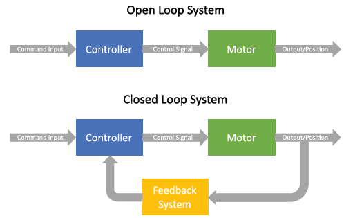
Figure 1. Image Credit: MKS Newport
Open-Loop Systems
Open-loop systems are not inherently rudimentary; even affordable open-loop devices can achieve extremely fine incremental motions.
Open-loop piezo-type devices can achieve nanometer-scale incremental motion. For example, picomotor open-loop systems infer the approximate position of a motion device without requiring an encoder. For a piezo device, the applied voltage indicates position.
However, the relationship is imprecise due to hysteresis and non-linearities inherent in commonplace piezo materials. For this reason, two picomotors will not always have the same standard picomotor step sizes.
Moreover, the slip/stick mechanism causes the step sizes to vary by load, as demonstrated in Figure 2. Still, for the same picomotor without a varying load, the step size remains the same.
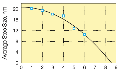
Figure 2. Image Credit: MKS Newport
An additional mechanism that influences Picomotor’s step size is direction, which is an effect of the difference between expansion and contraction of the piezo stack, as illustrated in Figure 3. The difference between forward and backward step size varies significantly, from 0% to over 100%, but always under 30 nm.
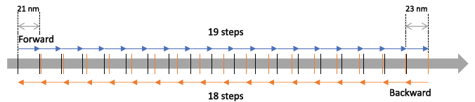
Figure 3. (Please note dimensions are not to scale). Image Credit: MKS Newport
Even with this step-size variability, position can still be adjusted at extremely small increments, enabling fine adjustments with exceptionally high stability. As illustrated in the example in Figure 3, although the picomotor moved forward and backward 18 steps, it will still be within 30 nm of the original position.
Of course, this is exacerbated at longer distances. Therefore, it is essential to consider using an open-loop picomotor for primarily small adjustments.
In addition, the loop on the main process under control should be closed. For instance, with mirror mounts in an optical beam path, the loop through the beam position should be closed using beam splitters and beam-position-sensing detectors, such as CONEX-PSD9 or CONEX-PSD10GE.
This will help users understand how to command the picomotors on the mirror to adjust the beam position. In applications like this, closed-loop picomotors would not have helped with the actual adjustment.
A good example of this is beam alignment within a laser cavity; it is impossible to manually adjust mirrors after the cavity is closed. At this time point, however, the adjustments should not be more than several steps in one direction or the other, making an open-loop picomotor ideal.
Closed-Loop Systems
Closing the position loop on a picomotor can be advantageous, especially when an application requires fully automated positioning, meaning the system is far from its optimal position. This next section will examine the encoder resolution and step size before providing specific examples.
On the closed-loop picomotor, the encoder resolution is slightly larger than the step size, allowing users to command the picomotor to go to a specific encoder count. Figure 4 shows how this is achieved.
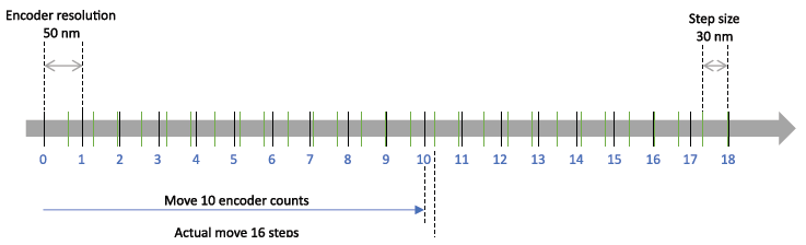
Figure 4. Image Credit: MKS Newport
In Figure 4, the picomotor is being commanded to move 10 encoder counts. To achieve this, the controller commands the picomotor to move 16 steps.
During the sixteenth step, the encoder hits the tenth count; however, due to the Picomotor’s fixed step size, it will finish the step and overstep the position of the tenth count. The worst-case scenario of this overstep leads to an error always less than the step size.
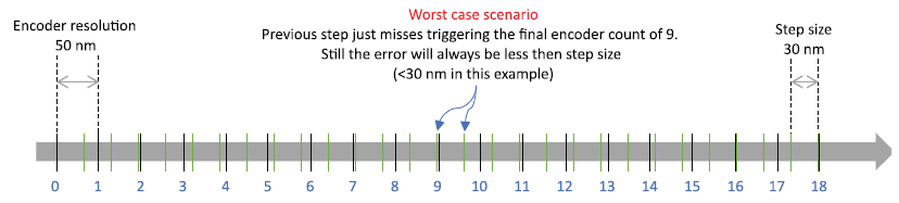
Figure 5. Image Credit: MKS Newport
The impossible encoder position makes it very difficult for the controller and user to go to a position based on encoder counts.
Now, consider the example from the beginning of this section: an application in which a linear stage carries a mirror. If the encoder resolution is smaller than the step size, using an actuator in an application becomes complicated.
Figure 6 demonstrates that the step size decides the position, and achieving a specific encoder count between steps mount is impossible. The linear stage must move between two positions, allowing the laser beam to hit one of two targets. Figure 7 illustrates the linear stage and picomotor in the two different positions, depending on which target the laser beam hits.
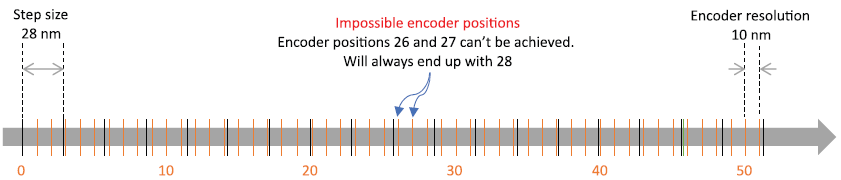
Figure 6. Image Credit: MKS Newport
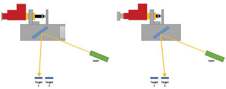
Figure 7. Image Credit: MKS Newport
If the move was 10 mm in this example, that would mean 200,000 encoder counts (based on 8311’s encoder resolution of 50 nm). However, as mentioned previously, the steps in either direction can differ greatly. The average step forward is approximately 21.4 nm and the backward step is 25.5 nm. That would mean moving forward would take 467,390 steps and moving backward almost 392,157 steps.
This results in a large discrepancy in the number of steps, making open-loop systems impractical unless beam-position-sensing detectors are available, as mentioned earlier. However, that would still be a much slower process, as users would have to go back and forth between moving the picomotor one step, checking the position on the sensor, and then repeating the process until reaching the desired position.
Closed-loop picomotors allow users to simply tell the controller the number of encoder counts to move the actuator, enabling optimization of the acceleration, speed, and deceleration to reduce the time it takes to get there.
Conclusion
As demonstrated above, the application determines which picomotor to employ: open or closed loop.
When exceptionally small, infrequent adjustments combined with a higher system-level feedback are required, such as beam-path position sensing, an open loop is more appropriate, and the added expense of a closed loop is unnecessary.
Closed loop is more feasible when the system must adjust to two or more well-known positions. In applications such as these, a closed loop can be very advantageous in reducing the time needed to move from one position to another.

This information has been sourced, reviewed, and adapted from materials provided by MKS Newport.
For more information on this source, please visit MKS Newport.