For a long time, Zernike polynomials have been considered an industry standard in the specification and analysis of an optical system’s wavefronts. The 37-term Fringe Zernike polynomial set is orthogonal when the pupil is circular and continuous.1 These are often employed to illustrate residual optical aberrations when a system is being tested.
When actual measurements are undertaken, the circular pupil is sampled and becomes non-continuous. While a discretely sampled pupil does not meet one of the requirements for orthogonality, when several points are sampled across the pupil, the resulting phase maps can be treated as continuous and the Zernike set is almost orthogonal.
The resulting coefficients are determined with considerable accuracy across a series of image iterations, even when camera noise is present. Dense sampling is commonly observed in a camera and interferometer setup.
Another test setup which is often used, is the use of a Shack-Hartmann wavefront sensor with related software to recreate the phase map from the spot array details. The wavefront is sparingly sampled and usually, Zernike coefficients are fit to ascertain the pupil’s aberration content.
This setup is a good option for circular pupils, even in cases where the sensor contains less than 50 discrete points across the aperture, or otherwise fails to meet an orthogonality condition. If the aperture is truncated, a second condition for orthogonality is therefore no longer met, so substantial errors may arise in the Zernike fit.2
Engineers utilizing a Shack-Hartmann setup for live feedback during system alignment may find it difficult to correlate Zernike coefficients with physical parameters. Within this article, restoring orthogonality to a truncated system is explored via a customized set of Zernike polynomials, specifically designed to be orthogonal over the geometry present in the system in question. This set is referred to as ‘Truncated Zernikes’.3
The increased stability of these Truncated Zernike coefficients is demonstrated over a series of noisy phase maps. It is not yet fully understood how these truncated coefficients are represented in a physical system. As a result of this, the test engineer may struggle to align a system without using a suitable optimization and image processing algorithm.
The implementation of Truncated Zernikes during system analysis’ design and tolerancing phases may provide valuable insight into a project, while considerably helping the alignment process.
Simulation
A simulation was created of the Shack-Hartmann phase map of a circular aperture which possessed fringe Zernike coefficients Z5 = 1, Z7 = 1, Z9 = 1 and Z16 = 1. Every other coefficient is zero while the aperture has a diameter of 38 pixels.
The aperture was truncated in one dimension to generate an asymmetric pupil, producing 30 noisy maps using a Gaussian noise consistent with a standard Shack-Hartmann test setup.
Every datamap was fit with the initial 25 fringe Zernike terms to ascertain precision of the fit across noisy images. Because the simulated Shack-Hartman test setup only sampled the pupil at 38 points across the pupil itself, fitting the phase maps with fringe Zernikes did not meet one requirement of orthogonality.
The aperture was truncated in one dimension so was not a unit circle. Additionally, a further condition of orthogonality is unmet, prompting significant errors when calculating low-order Zernike coefficients.
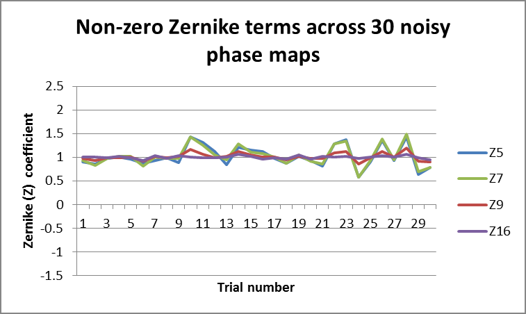
Figure 1. Fringe Zernike terms across 30 noise iterations of truncated pupil. Image Credit: Corning Incorporated - Advanced Optics
Figure 1 displays the non-zero Zernike term coefficients after being fitted to each of the noisy truncated pupils. The symmetric terms (Z9 and Z16) show a minor difference with noise but stay comparatively close to the noiseless coefficient of one.
The asymmetric terms show a notable variation where noise was added to the pupil, with the Z5 and Z7 terms varying by as much as 40% of the noiseless coefficient.
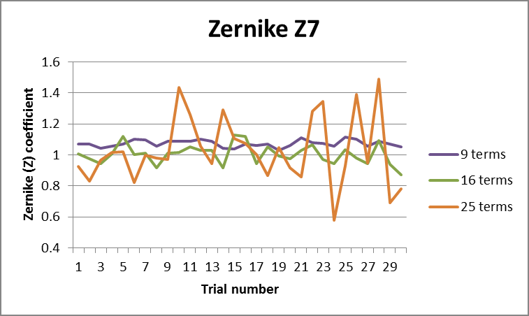
Figure 2. Fringe Zernike term Z7 from 3rd, 5th and 7th order fits to noisy truncated phase map. Image Credit: Corning Incorporated - Advanced Optics
Decreasing the order of the Zernike fit could be considered, meaning that only the first 9 or 16 terms would be included. Figure 2 illustrates the impact of this approach on Z7.
Fitting a decreased number of terms increases stability of the coefficient, and noise has a reduced impact when fitting 16 terms. This is increasingly prevalent with a 9-term fit. An in-depth inspection shows that the 9-term fit also features the inclusion of a bias over the noiseless Z7 term.
Aligning a system using data from a 9-term fit may result in an engineer being unaware of this bias, which could lead to errors into the lens endeavoring to drive this term to zero.
Rather than using Fringe Zernikes, it is possible to fit the pupil with an orthogonal polynomial set specifically tailored to the irregular geometry of the system in question. A Truncated Zernike set was used which was highly similar to the Fringe Zernikes, but instead was orthogonal over the truncated aperture.
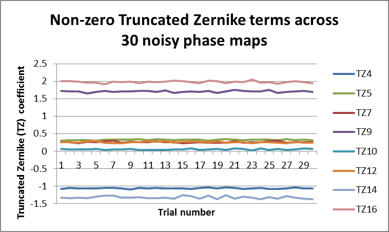
Figure 3. Truncated Zernike terms across 30 noise iterations of truncated pupil. Image Credit: Corning Incorporated - Advanced Optics
When one more orthogonality condition is met by utilizing the Truncated Zernike set, the polynomial fit becomes far more stable across various noise iterations, as can be seen in Figure 3. It should be noted however, that terms do not correlate directly between the two sets.
When comparing Figures 1 and 3, it should be noted that terms Z9 and Z16 retain an average value of 1 across the iterations of the pupil, while the truncated terms TZ9 and TZ16 maintain average values which are close to 2. Other truncated terms TZ4, TZ10, TZ12 and TZ14 possess non-zero contributions, as all of their corresponding Fringe Zernike terms were nominally zero.
Conclusions
As the pupil’s amount of truncation rises, Fringe Zernike coefficients become increasingly unstable with noise iterations. This makes the Truncated Zernike set more useful.
Additionally, Truncated Zernikes offer a more precise, representation of the data that is actually valuable, whilst disregarding the eliminated part of the circular pupil. Conventionally, Fringe Zernikes have been a helpful tool for test engineers due to their low order terms matching closely with the Seidel aberrations, generally employed in lens design and optimization.
The use of Fringe Zernikes in a truncated system may be deceptive to the alignment engineer however, as a pupil with a tiny wavefront RMS value could possess aberrations which are balanced in the used portion of the pupil. Meanwhile, contributions in the occluded region can merge to form unnaturally high values.
Zernike fits such as these are commonly unstable. Minor changes to the wavefront (such as noise) coupled with relying on Fringe Zernikes in these cases may result in sub-optimal alignment. The examples above have demonstrated that substituting the conventional Fringe Zernike set with a Truncated Zernike set, orthogonal over the geometry of the pupil, considerably increases the coefficients’ stability across noisy phase maps.
The use of Truncated Zernikes arrives presents a particular challenge when attempting to employ them as system alignment tools with real-time feedback. The Fringe Zernike set used to create the pupil simulation outlined above includes just four non-zero terms, with three of these being easy to correct via physical system parameters.
Z9 and Z16 are third- and fifth-order spherical terms, so these can usually be reduced by adjusting airspace within the lens.
Axial Z7 is a coma term, and this can be decreased by decentering a lens element in X and Y. When fit with Truncated Zernikes (Figure 3), the TZ terms do not possess a one-to-one correlation with fringe Zernikes, or with the Seidel aberrations present. When the same pupil is fit with Truncated Zernikes, it includes eight different non-zero terms.
These truncated coefficients manifest in several ways in a physical system, and this is not intuitive. A custom real-time software interface is needed, which is capable of displaying measured Truncated Zernikes, comparing these to nominal Truncated Zernikes for the system being tested.
References
- Shannon, R.R., The Art and Science of Optical Design. 1997: Cambridge University Press.
- Genberg, V.L., G.J. Michels, and K.B. Doyle. Orthogonality of Zernike polynomials. 2002.
- Aronstein, D., Truncated Zernike Polynomials. 2005, Corning Tropel internal document
Acknowledgments
Produced from materials originally authored by Kathleen Adelsberger, Stephen Mack, Ted Tienvieri and Tim Rich from Corning Tropel.

This information has been sourced, reviewed and adapted from materials provided by Corning Incorporated - Advanced Optics.
For more information on this source, please visit Corning Incorporated - Advanced Optics.