The microlithographic community has evolved through several generations of traditional refractive objective solutions for printing and inspection applications.
As the need for imaging demands for printing and inspecting increasingly smaller features has increased, there has been a growth in the use of higher numerical apertures and shorter wavelengths.
More glass paths, larger diameters and more refractive surfaces are now in use as refractive designs have become significantly more complex over time. At time same, there has been an increased demand for higher standards in a number of areas. These include:
- Transmission
- Axial thickness
- Radius of curvature
- Surface roughness
- Optical coatings
- Surface irregularity
- Material homogeneity
- Birefringence
It was found that more restricted sets of transmissive refractive materials presented new questions for optical designers and manufacturers to address when working at shorter wavelengths. For example, the use of shorter wavelengths reduces the number of viable glasses options available for color correction.
In the quest to lessen chromatic sensitivity, catadioptric design forms were found to offer a viable alternative. By using refractive and reflective elements, this alternative can harness much of the optical power contained in reflective components.
Catadioptric forms offer design alternatives that allow a continuation of performance enhancement that otherwise would face constraints when employing surface finishing, materials or coating technology which inhibits the ability to reach below 185 nm.
Tropel has developed catadioptric solutions that exclude the necessity for line narrowing the laser source applications at deep ultraviolet and vacuum ultraviolet wavelengths. This includes those used for printing and inspection at 248, 193 and 157 nm wavelengths.
Single and two material refractive design examples are shown for comparison.
Single Material Refractive Designs
While material options for designs below 300 nm wavelengths were initially restricted to the use of fused silica, single material design options at 248 nm in combination with excimer lasers have increasingly become the accepted industry standard.
Line narrowed excimer lasers and frequency doubled or naturally narrow lines of ion lasers are needed at high numerical apertures due to dispersive properties.
To compute the chromatic bandwidth, assuming the permissible degradation due to axial chromatic effects is within is one quarter of the Raleigh depth for a single material design, the following formula can be used:
 |
(1) |
In this instance, the following applies:
- n is the index of refraction
- λ is the central wavelength
- f is the focal length
- m is the magnification
- δn/δλ is the dispersion
- NA is the numerical aperture1
The use of single material designs for DUV photolithography at high numerical aperture with large imagery fields has led to the development of expensive lasers with complex line narrowing packages.
Single Material Resist/Process Development Objectives
When the industry made the transition to using i-line lithography from g-line lithography, resist technology did not keep pace when shorter wavelengths were employed to enhance lithography resolution.
DUV resist technology saw dramatic adjustments in chemistry when 248 nm lithography came to the market. Before commercial lithography tools became available, universities and research labs environments employed small field objectives in early resist development.
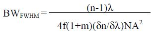
The objectives have been developed with SiO2 for use with excimer laser sources which have variable aperture stops. Lower numerical aperture settings mean these objectives could print beneficial imagery for process development with un-narrowed and partially narrowed excimer sources.
Using these designs at high numerical aperture settings to their maximum extent necessitates narrow bandwidths along with wavelength stabilization. Also, precise management of environmental factors including temperature and barometric pressure is important, but these controls can be expensive to apply on a small field evaluation tool.
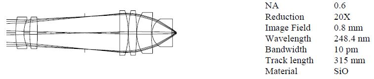
Figure 1. Single material small field projection optics for 248 nm resist evaluation. Image Credit: Corning Incorporated - Advanced Optics
Two Material Design Forms
Corrections to chromatic aberrations were attempted by the introduction CaF2 as a second material. Replacing positive ‘crown’ elements with CaF2 can lead to a reduction in chromatic sensitivity.
Currently, DUV wavelengths stable transmissive cements are not on the market, which means that air spaced doublet combinations are employed instead.
Use of appropriate materials such as SiO2 and CaF2 can lead to a reduction in chromatic aberrations. However, this can mean an increase in the number of elements as well as the overall length of the optical system (Figure 2).
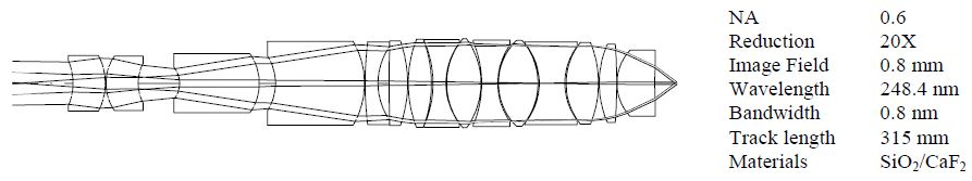
Figure 2. Two material small field projection optic for 248 nm. Image Credit: Corning Incorporated - Advanced Optics
Positive and negative elements both require increased power. However, centering and alignment tolerances mean that increased numerical aperture can become prohibitive with this design approach.
The higher the number of surfaces, the tighter surface tolerances become. Polishing steeply curved CaF2 surfaces to tighter tolerances also requires the use of deterministic polishing methods.
In addition, increased surface powers needed to achromatize can give rise to wider chromatic variations of aberrations, which in turn will limit performance. Field size is generally restrained by coma and lateral color. These can be hard to minimize due to a lack of symmetry about the stop which is necessary to reach telecentricity and lens reduction ratios not close to 1:1.
The increased complexity needed to attain achromatization is more challenging for shorter wavelength applications. The preferred crown material at 157 nm wavelengths is still CaF2.
As it does not transmit well enough at this wavelength, excimer grade SiO2 is not regarded as an option. At present, a second ‘flint’ material for achromatization has not been qualified for 157 nm applications.
Though BaF2 and SrF2 may be considered, due to their dispersion properties they may require greater complexity to achieve a similar achromatic correction that is attainable at longer wavelengths.
To counteract this increased sensitivity at shorter wavelengths, different design approaches with less complexity are needed. This is because the shortest of wavelengths that will transmit through refractive materials are employed.
Such design approaches enable the continued transition to shorter DUV and VUV wavelengths. Ideally, employing broader bandwidths will facilitate the use of more cost-effective un-narrowed excimer lasers and DUV lamps.
Catadioptric Forms
Catadioptric design forms give the option of reducing chromatic sensitivity with decreased overall complexity, and will incorporate refractive elements with some or most of the power in reflective components.
Use of single material catadioptric solutions which have the majority of the power contained in the reflective components was found to lead to the following:
- Reduced sensitivity to temperature
- Reduced sensitivity barometric pressure
- Being less sensitive to focus and magnification changes with wavelength2
Catadioptric forms tend to have better chromatic wavefront correction using less optical material path and fewer refractive surfaces when compared to equivalent refractive designs.
This is advantageous as materials, surface finishing and coating technology are not easily extended below 185 nm. Increased functioning at shorter wavelengths necessitates employing high purity crystals. However, these are difficult to develop at high quality and in volume.
To offset the effects of surface abnormalities and coarseness that can lead to flaring and scattered light, specialist polishing and coating processes are needed.
Newtonian Objectives
A Newtonian objective form was developed for use with line narrowed mercury arc lamps and un-narrowed excimer laser sources in step and repeat cameras.3 Single material designs are not sensitive to environmental variation in either temperature or barometric pressure.
This has led to the development of resist technology at 193 nm and 157 nm with almost perfect aerial imagery.4,5 This was achieved through combining refractive elements with a double reflective Mangin mirror.
Due to their benefit and coaxial simplicity, these flat field designs have the capacity to correct both design and manufacturing residual wavefront errors on a plano plate as part of a closed loop optimization procedure.
The design corrects the wavefront with an aspheric plate to >99% Strehl ratio. Strehl ratio is the intensity at the peak of the point image as a percentage of the peak of the aberration-free image, with the same vignetting and obscuration.
Measured wavefronts of actual assemblies have been corrected to >95% Strehl ratio.
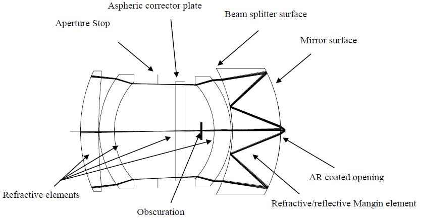
Figure 3. Major components in a small field Newtonian objective. Image Credit: Corning Incorporated - Advanced Optics
The form is limited to short working distances, and also necessitates the use of a central obscuration shield. This is to stop undesirable light transmitting from the reticle via the uncoated opening in the Mangin mirror to the image plane and thus exposing the wafer.
In addition, the shield can lead to a reduction in ghost image blur and flare light caused by multiple bounce reflections and scattered light from refractive surfaces. Otherwise, these would reach the image plane. Image plane flare in 193 nm systems has been found to be <2.5%.
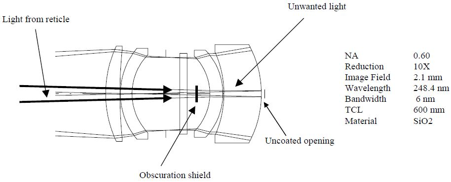
Figure 4. Central obscuration shields image plane from unwanted light passing directly through opening. Image Credit: Corning Incorporated - Advanced Optics
The design process must also factor in monitoring of light reflected from the beamsplitter and mirror surfaces, as the lens incorporates a beamsplitter.
Though this design form has a limitation due to throughput, stray light and ghost light analysis are used to track unwanted light as well as ensuring that the final design will prevent this unwanted light from exposing the wafer plane.
The beamsplitter limits the system transmission to <25%, while the required central obscuration shields <2% of the pupil area, and is on average <13% of the diameter of the pupil.
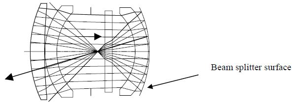
Figure 5. Reflected light off the beamsplitter travels away from the image plane. Image Credit: Corning Incorporated - Advanced Optics
However, high performance Newtonian solutions are achievable. The development of a second generation of catadioptric design solutions functioning at 157 nm are increasing numerical aperture as lithographers test the boundaries of optical lithography at longer wavelengths for resolving smaller geometries.6
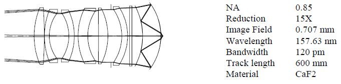
Figure 6. Small field 0.85 NA Newtonian objective for 157 nm resist evaluation. Image Credit: Corning Incorporated - Advanced Optics
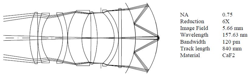
Figure 7. Mid field 0.75 NA Newtonian objective for 157 nm device level process development. Image Credit: Corning Incorporated - Advanced Optics
Figures 6 and 7 show a number of examples which incorporate larger numerical apertures and larger image fields.
Larger field solutions have been devised for device level process development.
Single Material Long Working Distance Inspection Objectives
Single material long working distance refractive designs are often needed to examine elements printed on reticles via protective pellicles. The necessity for a working distance that is greater than their effective focal length can be an obstacle overcome in these types of objectives.
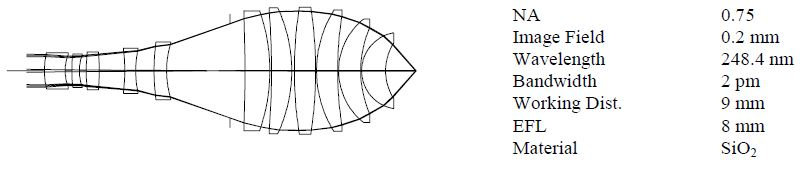
Figure 8. Long working distance objective for reticle inspection at 248 nm. Image Credit: Corning Incorporated - Advanced Optics
This necessitates the placing of a telephoto group at the front of the lens in order to enlarge the input beam.
As a result, the lens performance acts as if it has a longer focal length, and consequently, all aberrations, including chromatic aberrations, scale up in accordance with the telephoto ratio. This mean effective focal length in equation (1) is larger, which in turn reduces the bandwidth.
Two Material Long Working Distance Objective Form
As part of a process to boost the bandwidth of chromatic correction for this design form, CaF2 was introduced as a second material. Cemented doublet combinations were not considered. Positive ‘crown’ elements are replaced with CaF2 which aids in the reduction of chromatic sensitivity.
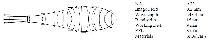
Figure 9. 0.75 NA long working distance objective for reticle inspection at 248 nm. Image Credit: Corning Incorporated - Advanced Optics
Chromatic advances are still not satisfactory for either un-narrowed excimer lasers nor cheaper broad-band emission sources, as this form in practice has both the limitations of the two material refractive form and the limitation of the single material long working distance form referred to earlier.
Schwarzschild Objective
The Schwarzschild objective is an all-reflective objective that affords both long working distance and broad chromatic correction. The form has notable limitations for most lithographic printing and inspection applications.
Aberrations are minimized near the concentric condition, however the central obscuration is large, typically >30% of the diameter.
Obscuration in the pupil and adds diffraction spikes is caused due to the use of a thin spider structure to support the small primary convex mirror. To achieve a reduction of the central obscuration, large amounts of spherical and severe off axis aberrations would need to be introduced.
Extending the design to higher NA (>0.60) requires at least one mirror to be aspheric to correct spherical aberration. However, with both mirror surfaces aspheric, off axis aberrations can also be corrected. This form has a very limited field of view due to field curvature, so different design approaches are required.
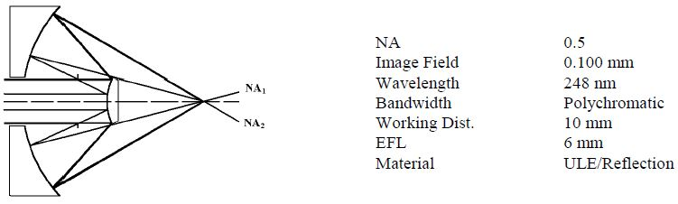
Figure 10. Long working distance two mirror reflective objective. Image Credit: Corning Incorporated - Advanced Optics
Design forms having central obscurations block some of the light that forms the imaging cone. The percent of the numerical aperture that is missing (NA1/NA2*100), where sin(θ) = NA, is calculated by determining the limiting aperture angle, (NA1) that passes without obstruction, divided by the full numerical aperture (NA2), as shown in Figure 10.
Long Working Distance µCatTM
The µCATTM design utilizes a ‘floating’ primary mirror. A Schwarzschild design generally holds the primary mirror in situ via the use of mechanical struts or ‘spiders’. By eliminating these struts, there can be a subsequent reduction in unwanted diffraction effects and scattered light.
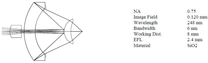
Figure 11. Long working distance high NA catadioptric objective with low % obscuration. Image Credit: Corning Incorporated - Advanced Optics
This design form was developed to offer an array of long working distance single material catadioptric design solutions for broader chromatic correction than is available in both single and two material all refractive designs.
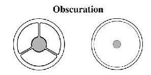
Figure 12. Comparing pupil and obscuration of Schwarschild and μCAT designs. Image Credit: Corning Incorporated - Advanced Optics
Similar to a Schwarschild objective in having a central obscuration, it integrates additional refractive surfaces as well as a reflective Mangin mirror surface. This allows for correction of aberrations at high numerical aperture.
This reduces the wavelength band for chromatic correction to 0.65 with a relatively minor central obscuration, usually 30%.
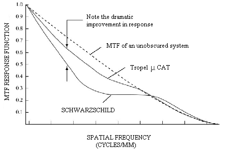
Figure 13. Best focus MTF Curve showing effect of central obscuration on the response function. Image Credit: Corning Incorporated - Advanced Optics
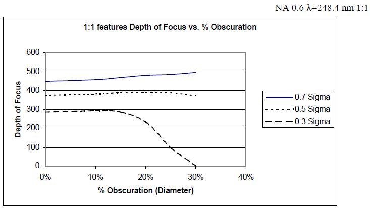
Figure 14. Effect that central obscuration has on partial coherent depth of focus for different pupil fill. Image Credit: Corning Incorporated - Advanced Optics
When used in conjunction with partial coherent illumination, catadioptric designs with a central obscuration have different performance characteristics.7 Central obscurations have minor effects on depth of focus with large pupil fill (sigma >0.5). When employing partial coherent illumination for small pupil fill (sigma <0.3) the useable depth of focus can be dramatically affected with increasing obscurations as shown in Figure 14.
Reducing Chromatic Aberration
Single material all refractive objective designs haves uncorrected longitudinal chromatic aberration, where shorter wavelengths will focus shorter than longer wavelengths.
To evaluate chromatic lens performance, the optical path difference over the pupil of the lens at different wavelengths can be plotted. In this instance, the horizontal axis represents the radial coordinate in the pupil of the lens at best focus on axis.
The vertical axis shows chromatic variation of focus and spherical aberration in waves. Perfect wavefronts in focus are straight lines parallel to the horizontal axis. The larger the wavefront error, the larger the optical path difference. As a result, the image blur will be larger.
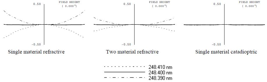
Figure 15. Comparing 0.75 NA design amounts of chromatic optical path difference (OPD) for narrow bandwidth. Image Credit: Corning Incorporated - Advanced Optics
One option to reduce the amount of longitudinal chromatic variation of aberrations is the use of two material refractive objective design can. Single material catadioptric design can minimize the longitudinal chromatic aberrations to almost zero over a narrow bandwidth range (Figure 15).
The addition of increased complexity can lead to heightened chromatic correction in two material refractive designs. When the power is almost completely or is completely in the mirrors, chromatic correction of catadioptric design forms can be significantly increased.
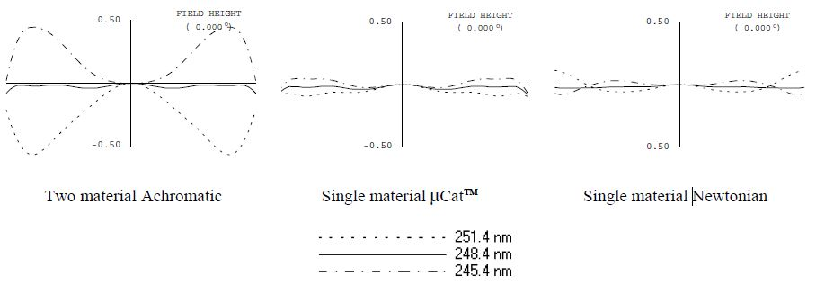
Figure 16. Comparing 0.6 NA design amounts of Spherochromatic optical path difference (OPD) for broad bandwidth. Image Credit: Corning Incorporated - Advanced Optics
For examples of designs with differing complexity and spherochromatic correction (Figure 16).
Summary
Comparing objective design forms with different focal lengths can be a difficult task. It may be more beneficial to utilize comparisons made at fixed numerical apertures, wavelengths and working distances. For example, Table 1 compares three objectives with greater than 1 mm working distance.
Table 1. Short working distance objectives chromatic bandwidth comparisons. Source: Corning Incorporated - Advanced Optics
| λ=248.4 nm |
| Type |
Single material |
Two material |
Newtonian |
| EFL |
14 mm |
15 mm |
25 mm |
| Bandwidth @ 0.60 NA |
0.011 nm |
0.8 nm |
6 nm |
| Bandwidth @ 0.75 NA |
0.008 nm |
-- |
4 nm |
A two material objective was found to correct a chromatic aberration for a source with more than ten times the bandwidth when compared to a single material refractive design.
A Newtonian objective form gave more than three orders of magnitude greater chromatic bandwidth when compared to a single material refractive design making possible the use of lamp sources.
Table 2. Long working distance objectives chromatic bandwidth comparisons. Source: Corning Incorporated - Advanced Optics
| λ=248.4 nm |
| Type |
Mono |
Two material |
µCatTM |
| EFL (mm) |
8 mm |
8 mm |
2.66 mm |
| Bandwidth @ 0.60 NA |
0.002 nm |
0.018 nm |
10 nm |
| Bandwidth @ 0.75 NA |
0.0015 nm |
0.014 nm |
6 nm |
Table 2 compared three lens types, with each having a working distance of more than 8 mm. Small increases in bandwidth were achieved when SiO2 and CaF2 are used. Approximately 10X improvement was achieved. The µCat design form corrects 1000X greater chromatic bandwidth when compared to the single material telephoto refractive design once scaling for focal length was factored in.
When compared to a refractive design of reasonable complexity, the two catadioptric forms were found to have higher chromatic correction. There is a small compromise in performance due to the central obscuration, however there are noticeable benefits.
Even when reducing complexity, continued usage at even shorter wavelengths is still possible. As there is a considerable cost advantage (because less expensive, broader band light sources can be utilized), catadioptric design forms are open for use in a wide range of markets.
References
- J. Bruning, “A Compact Optical Imaging System for Resist Process and Lithography Research,” SPIE Vol. 922, Optical/Laser Lithography, pp. 471-475, 1988.
- D. Williamson, et. Al., “Micrascan III, 0.25 um Resolution Step and Scan System”, SPIE Vol. 2726, Optical Microlithography IX, pp. 780-786, 1996.
- Patent No. 5,650,877 Imaging System for Ultraviolet Lithography.
- J.E. Webb and J. Nemechek, “Optical Fabrication Rises to the 193 nm Challenge,” Laser Focus World, p.75, February (1997).
- J.E. Webb, “All Calcium Fluoride Lithographic System Uses 157 nm Light,” Laser Focus World, p. 87, September (2000).
- J. Bruning, “Optical Lithography Below 100 nm,” Solid State Technology, November (1998).
- Martin McCallum, et. Al., “A Study of Obscuration in Catadioptric Lenses,” SPIE Optical Microlithography XIV, (2001).
Acknowledgments
Produced from materials originally authored by James Webb, Julie Bentley, Paul Michaloski, Anthony Phillips and Ted Tienvieri from Tropel Corporation, with thanks to Dr. John Bruning, Louie Denes, Tim Rich and Dave Young.

This information has been sourced, reviewed and adapted from materials provided by Corning Incorporated - Advanced Optics.
For more information on this source, please visit Corning Incorporated - Advanced Optics.