A typical product line of lenses was adapted through the addition of an extra element in contact with immersion fluid. This adaptation enables this product line to be migrated from dry objectives to immersion objectives, providing numerical apertures which of more than 1.0, resulting in higher resolution and an increased depth of focus.
The Catadioptric Design Form
The lens1 displayed in Figure 1 is a modified Schwarzschild objective which enables superior numerical aperture wavefront correction alongside decreased central obscuration via all spherical surfaces.
First, light passes through the uncoated section of the R1 surface of a Mangin mirror, before passing through refractive surfaces R2 and R3. Next, it reflects off the R4 Mangin mirror surface section of the three surface multifunction part.
If the radius of R4 is lower than R5, rays then reflect back through R3 and R2 until they are reflected off R1’s larger reflective surface. Light is able to refract through R2 and R3 again with greater ray heights enabling light to refract through the transmissive section of R5, doing so above the R4 mirror’s obscuring surface.
This procedure removes the need for a supporting spider to keep the small primary mirror in place within an all-reflective objective.2 This form of catadioptric objective offers a small central obscuration, generally smaller than 20% of the total numerical aperture.
Adding refractive surfaces provides the variables required to account for monochromatic aberrations at higher numerical apertures, introducing chromatic aberrations which need correction while limiting the operational bandwidth.
Objectives of this form may be achromatized through the use of a single material over the free-running spectrum of un-narrowed EXCIMER lasers at DUV and VUV (Nitrogen) wavelengths.
The addition of refractive components before, in between and after the double Mangin mirror cavity enables high numerical aperture solutions that have long working distances.
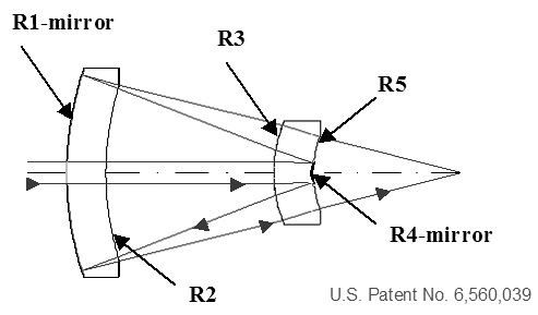
Figure 1. Catadioptric design form. Image Credit: Corning Incorporated - Advanced Optics
μCat® Objective Family
The lens displayed in Figure 2 is one example of this form of extension. This particular objective allows for a 0.75 numerical aperture which covers 120 μm field of view, possessing 8 mm of working distance.
Here, diffraction limited solutions2 which are working at 248, 193 and 157 nm have been corrected for each of these laser sources across their free-running spectral bandwidth. The extended working distance is certainly beneficial in a wide range of applications, such as photomask inspection through a protective pellicle.
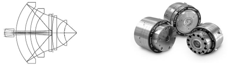
Figure 2. The μCat® Panther catadioptric objective. Image Credit: Corning Incorporated - Advanced Optics
Corning Tropel has successfully developed this design form to create a family of objectives which ranges from 0.52 – 0.90 numerical aperture. This family of objectives is called μCat® and is a trademarked name.
Aquacat™ with Plano Surface Interface
A helpful and perhaps unexpected advantage of the long working distance is the extra space available, which enables the addition of an element which allows the light to couple into an immersion fluid, for example water. This increases the numerical aperture by changing the index n, of the image medium from air to water since NA=n*sin (θ).
Two approaches are explored here. The design displayed in Figure 3 adds a convex-plano element, meaning that even a small amount of refraction at each of this element’s surfaces introduces aberration.
Expanded view at infinite conjugate
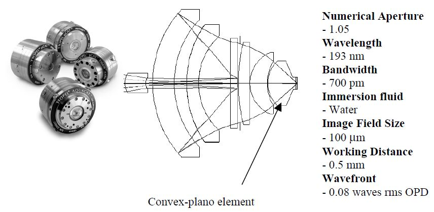
Figure 3. Immersion micro-objective with plano interface to fluid. Image Credit: Corning Incorporated - Advanced Optics
Altering the curvatures of the elements after the stop in the lens allows for compensation of the aberrations over a 100 μm field of view (Figure 4). The wavefront performance is restricted by a compromise of field size and field curvature.
193 nm Excimer Laser - Free running un-narrowed spectrum
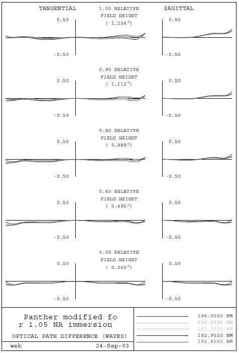
Figure 4. Optical path difference (OPD) - plano interface. Image Credit: Corning Incorporated - Advanced Optics
The catadioptric objective is able to correct the 700 pm FWHM bandwidth of the EXCIMER laser source with ease, with bandwidth being optimized over the range from 192.65 to 194 nm.
There are other benefits to using a broad bandwidth achromatization via a single material. The objective sees a reduction in sensitivity to environmental changes, such as barometric pressure and temperature, with fluid index variations of +/- 0.0001 being tolerated with no issues.
The index of high purity water was found to be 1.436 at 193.3 nm wavelength.3 The objective performance here can be optimized at 1.05 numerical aperture. This means that all elements and spherical components which had defined the Mangin cavity previously are suitable for use without modification.
This objective design can be extended further in NA by aspherizing the convex-plano element. It is possible to minimize alignment sensitivity by aspherizing the convex surface. The numerical aperture may be extended to 1.15 NA at the limiting apertures of the original design. This design form can be extended beyond 1.2 NA if required.
The first objective manufactured for 1.05 NA featured an extra element which provides a plano interface, as well as a 0.5 mm working distance in water.
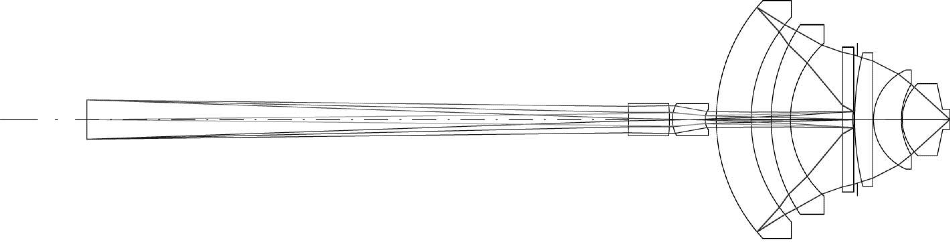
Figure 5. Finite conjugate AquaCatTM. Image Credit: Corning Incorporated - Advanced Optics
An extra focusing lens is added in front, giving this a finite conjugate objective which has a 90X reduction ratio at a 210 mm track length (Figure 5). To make alignment more straightforward, the objective and tube lens combination is specifically designed so that the entrance pupil is focused at the image plane prior to the objective being installed.
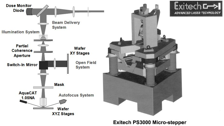
Figure 6. Exitech Micro-stepper. Image Credit: Corning Incorporated - Advanced Optics
The objective is an elemental of an optical system which incorporates a beam delivery and illumination system, installed into a Micro-stepper4 (Figure 6). This is employed to study resist image characteristics for hyper-NA through the use of a range of polarization and illumination techniques.
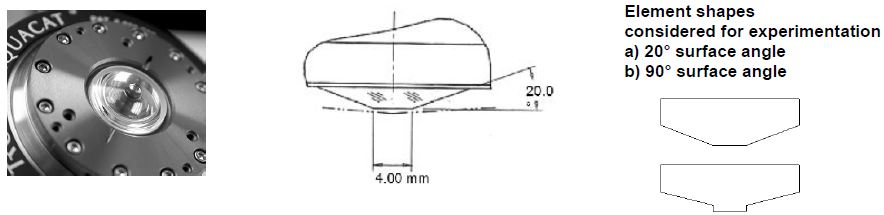
Figure 7. Element shapes considered for Immersion. Image Credit: Corning Incorporated - Advanced Optics
A number of collaborative experiments4 were conducted to ascertain the optimal element shape for the retention of immersion fluid. Numerous element styles were supplied to researchers from Rochester Institute of Technology (RIT) so that they could determine the most ideal shape for fluid adherence to the lens’s plano surface. The surface shape with sharp corners was selected (Figure 7).
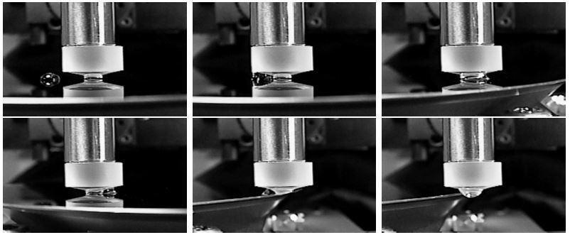
Figure 8. Element shapes considered for Immersion. Image Credit: Corning Incorporated - Advanced Optics
Figure 8 displays a sequence of images within which the element demonstrates good wetting characteristics. A bead of water is contained by the sharp edges and the plano face of the fused silica element, being repelled off by the resist. It is evident here that the element is hydrophilic while the resist coated silicon wafer is hydrophobic.
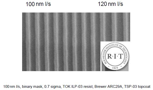
Figure 9. Binary mask images of equal lines and spaces. Image Credit: Corning Incorporated - Advanced Optics
Corning Tropel is collaborating with RIT and Exitech Ltd. on this program. They are working together to establish RIT as a technology center for immersion research. Early results on the tool have highlighted that resolving 100 nm lines and spaces is possible, without illumination or polarization enhancement techniques (Figure 9).
Aquacat™ with Concave Surface Interface
RIT4 has shown that further increasing the numerical aperture using alternative transmissive immersion fluids is possible, where these have a higher index of refraction at 193 nm using Smith-Talbot interference lithography.4 Within the experiments, resist images which are smaller than 40 nm have been formed.
In order to fully explore the advantage of fluids possessing higher indices, a modified AquaCat™ design enables the final surface to curve to a concave shape. While the index difference between fused silica and water is small in comparison to that of silica and air, even the smallest index mismatches have the potential to introduce large aberrations.
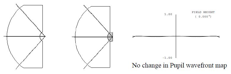
Figure 10. The concave surface normal to exiting rays does not refract. Image Credit: Corning Incorporated - Advanced Optics
When the rays leaving the last surface of the lens are exactly normal to the surface (Figure 10), refraction and therefore aberrations are not present. This is strictly true on axis, but is tolerable within a wavefront specification over a restricted field of view.
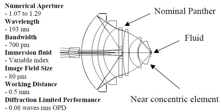
Figure 11. Immersion micro-objective with concave surface interface to fluid. Image Credit: Corning Incorporated - Advanced Optics
Figure 11 highlights a 193 nm immersion design coupled with index fluid varying over a range from 1.44-1.74 is shown. A Panther MicroCat™ objective is utilized with an additional element, as can be seen. This element is almost concentric in order to lower instances of ghost reflections while balancing correction over an 80 μm field of view.
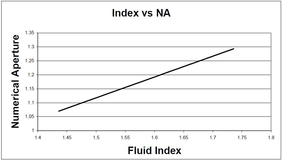
Figure 12. Fluid index vs. numerical aperture. Image Credit: Corning Incorporated - Advanced Optics
Within this particular design, the index may vary whilst the numerical aperture of the lens is proportional to the fluid’s index (Figure 12). Correction is maintained over the range of index. The numerical aperture and the resolution will both increase, should a fluid be found that can accommodate high transmission at 193 nm.
An examination was undertaken of the design wavefront at the extremes of probable index variation. The two graphs (Figure 13) display the way in which the wavefronts vary as a function of field for these two cases, both of which are extreme. It is possible to achieve wavefront errors under 0.08 waves rms optical path difference (OPD) within the range of 1.44-1.74 indices over an 80 μm field of view.
193 nm EXCIMER Laser - Free running un-narrowed spectrum
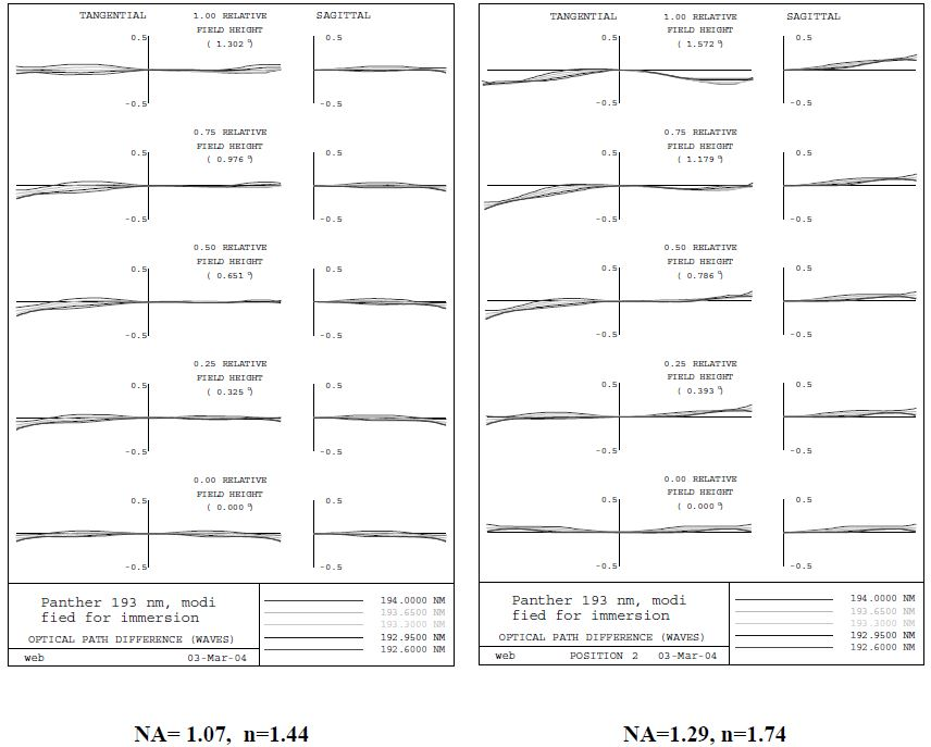
Figure 13. AquaCatTM design wavefronts with varying index. Image Credit: Corning Incorporated - Advanced Optics
Conclusions
New and creative design solutions for immersion lithography research have been designed and developed by building on μCat™ Panther objectives. Corning Tropel has been able to manufacture and deliver a 1.05 NA 193 nm objective, working in collaboration with RIT and Exitech Ltd., in order to demonstrate hyper NA imaging in resist.
This platform will be used to explore variations of mask, illumination and polarization. It will be possible to use this flexible design approach to study imaging characteristics of different immersion fluids over a wide range of numerical apertures.
References
- U.S. Patent No. 6,560,039 Double mirror catadioptric objective lens system with three optical surface multifunction component, Webb, et al., Sept. 26, 2000.
- J.E. Webb, et al., “Optical Design Forms for DUV&VUV Microlithographic Processes”, SPIE Vol. 4346_55, Optical Microlithography, pp 566-567, 2001.
- J. Burnett, et al., “Optical properties of water for 193 nm immersion lithography”, 2nd ISMT Immersion Lithography Workshop, Almeden, California, July 11, 2003.
- B. Smith, “Water based immersion lithography”, 3rd ISMT Immersion Lithography Workshop, Los Angeles, California, January 27, 2004.
Acknowledgments
Produced from materials originally authored by James Webb and Louis Denes from Corning Tropel Corporation, with thanks to Bruce Smith, RIT; Malcolm Gower and Julian Cashmore, Exitech Ltd.; Dave Young, John Bruning, Lisa Rich and the litho team from Corning Tropel.

This information has been sourced, reviewed and adapted from materials provided by Corning Incorporated - Advanced Optics.
For more information on this source, please visit Corning Incorporated - Advanced Optics.