In a previous article the design of a MWIR continuous zoom twith significant zoom range (>30X)1 was outlined. There were a number of challenges that were addressed in the design phase. In this article, what it takes to tolerance and build a system of that complexity is discussed.
These challenges also had to be overcome in the tolerancing and building of the zoom assembly. The biggest obstacle was developing a strategy which would enable the zoom focus to be continuous.
The large zoom range produced the condition of the zoom groups moving through the 1X magnification case. In the literature, discontinuities about this point have been well documented. Some of the parts of the mechanical design which were required to acquire the final optical system are also discussed.
Actual Design
It is usual to base the design on a particular camera with many IR optical designs. The cold stop of the camera must act as the aperture stop of the optical system. The optical prescription was easily migrated to a final design after the camera specifications were fixed.
Some newer design tools were used and several aspheric surfaces were actually removed from the earlier design. This helped to decrease the complexity and cost of the design. The zoom system shown here is based upon the specification presented in table 1.
Table 1. Characteristics of the optical design presented. Source: Corning Incorporated - Advanced Optics
| Characteristics |
Value |
| Zoom Range |
>30X |
| Focal Length Range |
15.25 - 456 mm |
| Spectrum |
3 - 5 µm |
| F/# |
4.5 |
| Image Plane Diagonal |
12.3 mm |
| Pixel size |
30 µm |
| Front Element Diameter |
120 mm |
| Total Track |
353 mm |
| Distortion |
<0.5% |
| Transmission |
>70% |
| Number of Diffractives |
1 |
By decreasing the F/# and image plane size the design form can be migrated to other camera specifications. The design also accommodates mirror placements for different packaging needs.
The zoom range shown here is 30 X, but the limitation is not mechanical. The Narcissus and illumination uniformity will begin to dominate, but the focus and MTF performance is maintained for wider fields of view.
The design contains multiple aspheric, and one diffractive surface. The use of aspheres is not cost prohibitive, as the optics are diamond turned. They are crucial for the performance of this type of zoom system, due to the small overall length2.
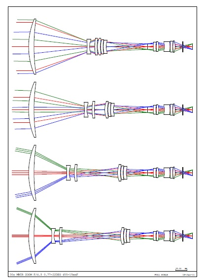
Figure 1. The layout shows the smooth path of the zoom groups throughout the range. It also shows that the WFOV is not limited by any glass to glass collisions. Image Credit: Corning Incorporated - Advanced Optics
Performance
The nominal system has very low distortion and is nearly diffraction limited across the zoom range. As previously discussed, the design form was controlled to set up favorable conditions to have low sensitivities. The degradation of the wavefront will not significantly change from the nominal design because of proper tolerancing.
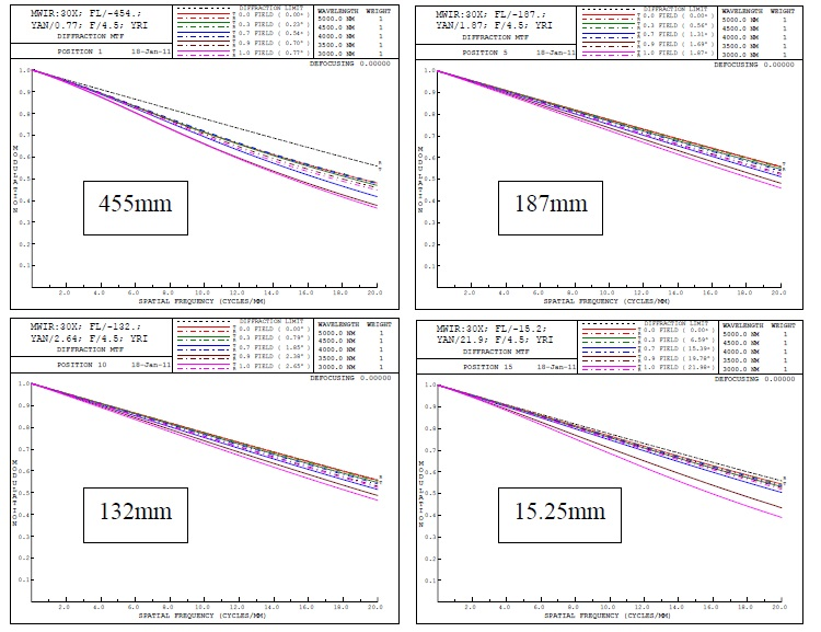
Figure 2. The MTF plots shown are out to Nyquist of the designed camera. The system is close to the diffraction limit for the entire zoom range and for the full field. Image Credit: Corning Incorporated - Advanced Optics
Additionally, for the entire 30 X range, the distortion of this zoom system is less than 0.5%. The distortion over the full focal length range is shown in Figure 5.
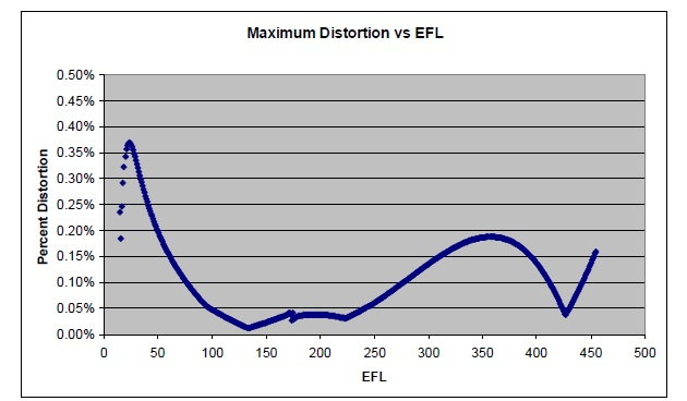
Figure 3. The distortion of the system is low through the entire zoom range. Image Credit: Corning Incorporated - Advanced Optics
Close Focus Range
Close focus was needed for this system. This was not a big concern of the design due to the ability to move both moving groups independently. It was discovered that, at a target 25 meters away, the WFOV had no loss of contrast. This target range could be acquired with a shift of one of the zoom groups for the NFOV.
Thermal Compensation
The optical system was designed to handle a thermal range from -40 °C to +60 °C, as outlined in the prior paper. By repositioning the zoom groups, the performance over this thermal range was preserved.
Tolerancing
Predicted Results
An optical designer must always evaluate the sensitivities of the design. A design which has a lower nominal performance but low sensitivities may be better than a nominal design with high sensitivities.
The aberrations throughout the design process could be controlled, which resulted in a system with good manufacturability. In the tolerancing of the zoom system, each zoom group would be driven independently, which enabled Corning Glass Technologies to have two free compensators.
They wanted the building and compensation of the system to be as straightforward and simple as possible. This was accomplished by treating the objective and zoom as different entities from the re-imager group.
Maintaining Continuous Focus
The design attained a continuous zoom range by very examining the 1st order of the zoom groups carefully, in addition to thorough examination of the 1 X magnification positions.
This care had to be carried through to the tolerancing and build process. As the tolerances on the center thickness and individual surfaces would lead to a change to the first order of the zoom, how to compensate for these changes had to be considered carefully.
With the alteration in focal length of each of the zoom groups, Corning Glass Technologies had to be able to handle building a continuous zoom system even though the first orders of each system would be a little bit different.
They discovered that this could be acquired without utilizing measured element data in a design program or measuring the focal lengths of each of the zoom groups. This enables the build process to move more smoothly.
The build strategy will consider optical effects when the zoom groups are moved through their nominal paths to establish how adjustments should be made.
Controlling Boresight
One crucial requirement of most IR zoom systems is very good boresight. This was a huge challenge, with a significant zoom range and zoom groups moving axially up to 75 mm.
The tolerances and alignment scheme have enabled the boresight to be below ½ a pixel, without any internal compensation. This error could be reduced further with compensation.
Mechanical Design
The housing is made of upper and lower halves, each one supports one of the two drive mechanisms. A camera adaptor can be produced to fit nearly any mount type, or the housing design can be easily altered for special applications.
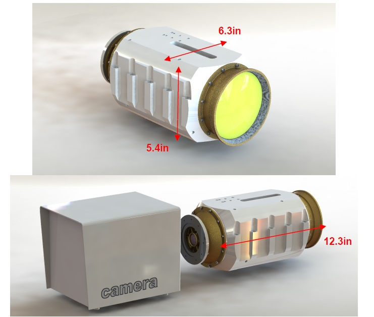
Figure 4a-b. Envelope dimensions. Image Credit: Corning Incorporated - Advanced Optics
The IR lenses are bonded in their cells using athermalizing bond gaps. Both movable lens groups utilize a carriage design which is similar, guided by two rails each. Each primary rail locates the carriage by a collinear pair of linear bearings.
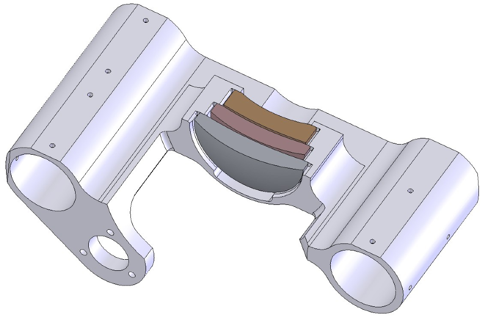
Figure 5. Integral lens cell and carriage. Image Credit: Corning Incorporated - Advanced Optics
The single linear bearing and secondary rail stop the carriage subassembly from rotating about the first rail. During assembly the rails are aligned as needed. Each carriage is positioned along the optical axis using a lead screw and anti-backlash lead nut which is flange-mounted to the carriage.
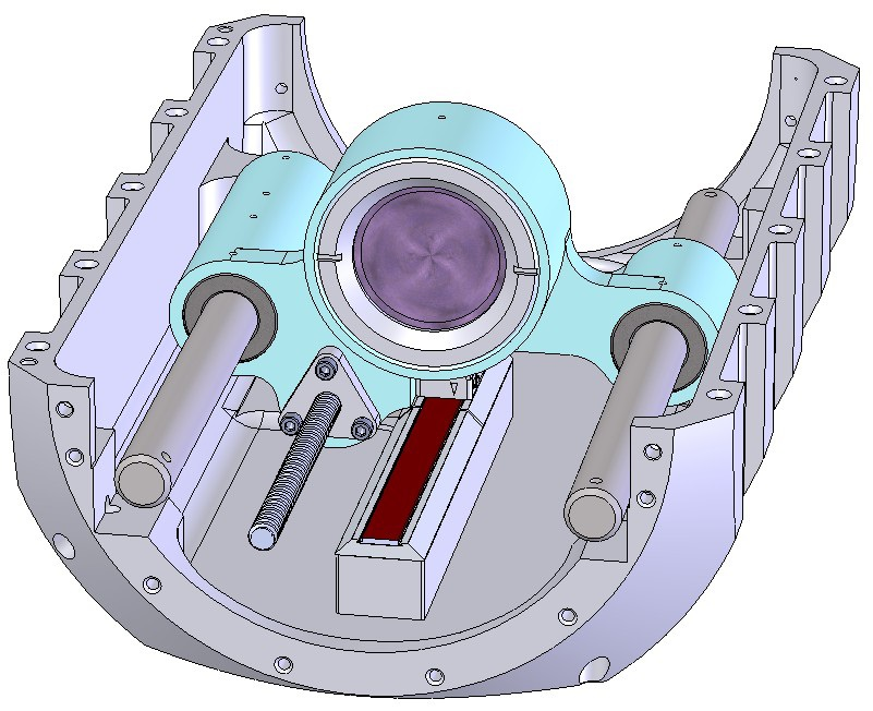
Figure 6. Rail guides and lead screw drive, which is similar for both moving lens groups. Image Credit: Corning Incorporated - Advanced Optics
The lead screw is supported with a pair of preloaded duplex bearings at the driven end, while the other end is constrained radially by the lead nut. The motor size, lead dimension, and gear reduction are chosen to balance actuation speed and electrical needs with positioning accuracy. The actuators are able to operate at 100% duty cycle with <25 °C temp rise of the motor.
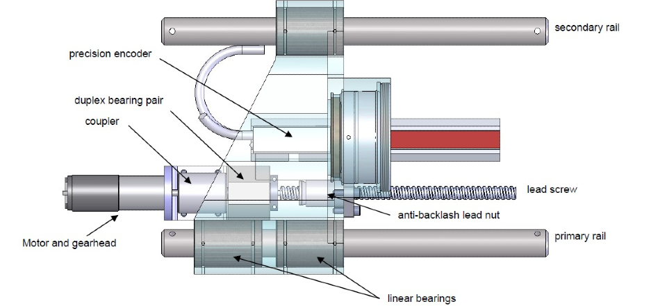
Figure 7. Major components for half of the zoom mechanism. Image Credit: Corning Incorporated - Advanced Optics
Summary
Through sound design principals Corning Glass Technologies have shown how to build a MWIR zoom system which has a very large zoom range with continuous focus. The system was toleranced with the build strategy in mind. The electrical and mechanical designs have produced a system to meet the customer requirements.
References
[1] Sanson, Mark, Cornell, Jim, “MWIR Continuous Zoom With Large Zoom Range,” Proc. Of SPIE. Vol. 7660, 76601X-1-12 (2010)
[2] Betensky, Ellis, “The role of aspherics in zoom lens design”, SPIE Vol. 1354, 656-662 (1990)
Acknowledgments
Produced from materials originally authored by Mark C. Sansona, James Cornell, Brian Roy, Stephen Herbert, Ken Woodard and Kent Sawyer from Corning Incorporated.

This information has been sourced, reviewed and adapted from materials provided by Corning Incorporated - Advanced Optics.
For more information on this source, please visit Corning Incorporated - Advanced Optics.