The marketplace for optical components has numerous global suppliers who all possess capabilities which are similar. The Photonics Buyers Guide1 has a list of 1,311 suppliers of optical components.
All 1,311 suppliers do not possess the same capabilities or products, but the large number demonstrates the breadth of potential optical suppliers in the optics marketplace. One can observe this expansive marketplace at the SPIE Photonics West trade show. There were over 1,300 registered exhibitors in 20182.
By adding capabilities and striving toward vertical integration, a company is able to distinguish itself from all of its competitors. A company which is vertically integrated can give it’s customers more value by reducing costs, improving lead times, and simplifying the supply chain.
Vertical integration is the combination, under a single ownership, of two or more stages of production or distribution (or both) that are usually separate2 according to the traditional economic definition.
At a high level, optical systems are usually made up of a number of optical elements which are held together with one or more mechanical elements. The details of each optical system will be established not only by the specification required, but by the manufacturing capabilities of the supplier.
Advantages of Vertical Integration
There are numerous suppliers in the optics field. Some coat optic but do not polish. Some polish curved surfaces, but do not coat optics. Some only polish flats. Some can do all of the above but do not perform any assembly.
It can be challenging for a company procuring an optical lens assembly to know where to begin due to the varying degree of capabilities. From a procurement standpoint, the easiest thing to do is to find a supplier who delivers on all the required steps, one who is vertically integrated.
For this article, an optical system supplier is considered vertically integrated with both machine power (optical and mechanical finishing, thin film coating) and people (many engineering disciplines) if they have the following capabilities:
Manufacturing Capabilities
- Optical assembly
- Optics fabrication
- System test
- Mechanical fabrication
- Thin film deposition
Design and Engineering Capabilities
- Metrology
- Optical
- Manufacturing
- Mechanical
- Thin film
Possessing all of these capabilities within one building, or even one organization is advantageous to both the customer and supplier. The customer is able to find a single business to work with and give them a specification document or outline the requirements of the system in even broader terms.
The vertically integrated supplier is able to design an optical system which meets these requirements. Within the supplier, optical designers can get quick feedback from their fellow engineers in other disciplines.
This enables faster design turn around. For instance, in a vertically integrated supplier, an optical designer can walk within the same building to other engineers and confirm things like:
- Manufacturing tolerances
- Number of elements which can fit in the coating chamber
- Acceptable lens diameters for polishing machines and coating chambers
- Optical element edge thicknesses
- Expected thin film performance
- Optical surface runouts based on a particular mounting strategy
These are just a few crucial items which should be considered. To collect this amount of information from array subcontractors could take many days or weeks after setting up conference calls or waiting for email responses.
The ability to efficiently design and build a system based on known capabilities is an advantage of having all of the manufacturing and engineering resources in one organization.
This process is known as DF/X, Design For X, where X can be safety, cost, manufacturability, assembly, serviceability, etc. The effective use of this process leads to increased quality, lower cost, quicker product development, and shorter lead times.
Design for Manufacturing and Concurrent Engineering
Concurrent engineering is enabled by being both vertically integrated in engineering personnel and manufacturing processes. It is the practice of concurrently developing products and their manufacturing processes.
Furthermore, this permits product development teams which include both engineering and manufacturing personnel. This eliminates instances where engineers made assumptions about processes and capabilities.
The design phase of a product life cycle can be more effective with this continuous communication between engineering and manufacturing. There are a number of design for manufacturability guidelines which can be utilized in effective opto-mechanical system design4:
- Minimize tooling complexity by concurrently designing tooling
- Understand manufacturing problems/issues of current and past products
- Understand tolerance step functions and specify tolerances wisely
- Specify optimal tolerances for a robust design
- Adhere to specific process design guidelines
- Design for fixturing
- Minimize cutting tools
- Minimize setups
- Specify parts from reliable sources
- Design for easy fabrication, processing, and assembly
All of these actions can lead to better quality, a faster manufacturing time, and lower cost. The result is a more competitive product in the marketplace. The ability to accomplish these efficiencies also results in new product innovation and introduction by better understanding capabilities and processes.
Buzzell demonstrated that a high level of integration corresponds to high rates of new product introduction as reported in the Harvard Business Review3. In optical systems, once a system passes beyond prototype production, it is difficult to make significant cost reductions without sacrificing quality and performance.
The product design determines eighty percent of the lifetime cost of a product4. Optical elements cannot be polished faster without sacrificing quality like roughness or surface irregularity. One technique which is used to decrease cost is with batch processing, typically in thin film coating, polishing, or molding.
Batching opportunities may be possible, but can only be performed with certain optical element geometries, making this cost saving opportunity not widely available to all systems. Fitting many parts into a coating chamber is a technique which can be used to perform batch processing.
The drawback to large batches in coating could be coating performance uniformity across parts or the chance for an upset during the coating process, which would require rework or scrapping of all the optics.
Moving to molded solutions in plastic or glass could be viable for visible and infrared wavelength systems, but there are some potential sacrifices in performance of polarization properties, surface quality, and thermal properties to consider.
The result is that the largest cost savings are designed into the system from the start, not implemented in a cost saving strategy afterwards. Trying to reduce costs by outsourcing more parts or activities to decrease overhead costs will still result in the same effective overhead cost.
All of the downstream suppliers and subcontractors are likely to have a similar overhead structure, a pictorial example of this can be observed in Figure 2. Vertical integration and concurrent engineering can help reduce costs upfront in the design due to the inability to save costs in this manner.
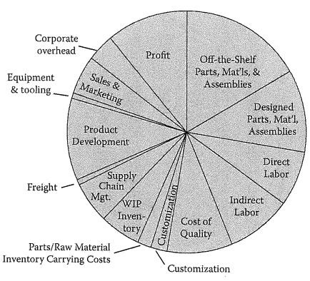
Figure 1. Example Product Cost Structure4. Image Credit: Corning Incorporated - Advanced Optics
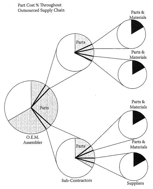
Figure 2. Product Cost Structure with Suppliers4. Image Credit: Corning Incorporated - Advanced Optics
Example of Design for Manufacturing in Practice
The need for a vertically integrated supplier grows with demanding system specifications and system complexity. In this instance, best practices of concurrent engineering were utilized to develop a manufacturing strategy to build the tube lens shown in Figure 3.
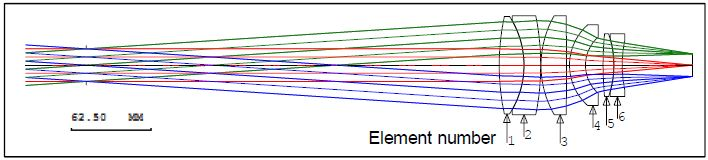
Figure 3. Tube lens. Image Credit: Corning Incorporated - Advanced Optics
This tube lens works simultaneously with a high NA objective. The combined system, tube lens and objective, is only permitted in small variations in distortion of 0.65 microns. A monte carlo analysis was performed before manufacturing the lens system.
The results showed that the objective would yield a 0.02% change in magnification, which would lead to too much distortion for this application. Furthermore, the system's environmental conditions would also add unacceptable magnification variations.
There were a number of engineers who worked to finalize the optical design. The optical design engineer worked with an optical fabrication process engineer to review material properties (water resistance, hardness, etc) and achievable tolerances, and finalize lens aspect ratios.
At the same time, the optical design engineer also worked with a thin film engineer to assess the angles of incidence, system spectrum, material properties, and transmission requirements.
Additionally, there was a review between manufacturing engineering and optical design regarding doublet assembly. The advantage of a vertically integrated engineering department is that it enables concurrent engineering even at the start of the design process, as illustrated here.
An external design consultant could be capable of a similar design, but the value added of fruitful and fast interaction and design feedback pays numerous dividends: No assumptions based on rules of thumb, better chances of success, and team buy in that the design can be manufactured.
Before the discussion of magnification compensation at least four engineers have reviewed the design already. The need for magnification correction resulted in the requirement for a moveable element(s) in either the tube lens or objective.
It was established by the optical design engineer that the magnification correction should occur with the tube lens as the objective is primarily optimized for wavefront performance. The system magnification sensitivity to element shifts along the optical axis is shown in Figure 5.
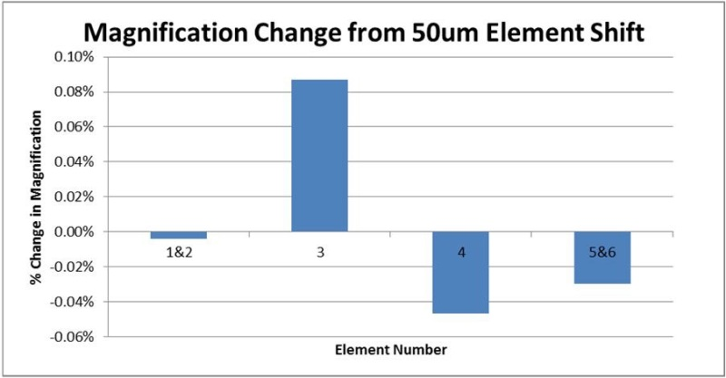
Figure 4. Magnification Sensivitiy. Image Credit: Corning Incorporated - Advanced Optics
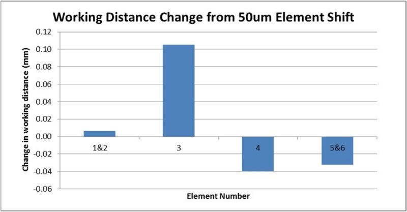
Figure 5. Working Distance Sensitivity. Image Credit: Corning Incorporated - Advanced Optics
The engineering team determined that the elements 5-6 doublet would be the ideal candidate to do the magnification correction by utilizing the sensitivity information and previous design experience with moveable elements.
Even though elements 3 and 4 would have needed less motion for magnification compensation, the 5 & 6 doublet location at the outside of the lens stack enabled easier implementation of motion control.
The tube lens working distance, the distance from the last element to the image plane, also changed as a result of moving an element. Other system requirements forced the camera to be in a static position.
To keep focus at the camera sensor, this forces the need to move the entire tube lens as doublet 5&6 was in continuous motion, similar to how a zoom lens works. The motions had to be performed actively to account for changing environmental conditions.
All engineering disciplines had to be involved as a result of the requirement to move doublet 5 & 6 and the whole tube lens assembly. An optical engineer supplied the resolution requirements and motion range.
In order to find motion controls and mechanics to meet the motion specifications electrical and mechanical engineering worked together. Manufacturing engineers helped to guide the design with insights as to how the product would be assembled.
One method to permit the best assembly practices was to 3D print the assembly in piece parts. This allowed engineers to practice building their own designs without the requirement for custom machined parts.
Assembly of a prototype design and 3D printing also enabled fast design iteration in days, instead of the multiple weeks it would have taken to produce or procure custom machined parts.
There are noticeable mechanical changes between an early 3D printed model and the rendering of the final iteration, as seen in the figure. Mechanical and manufacturing engineers also worked together to alter the groupings of the lenses in mechanical cells.
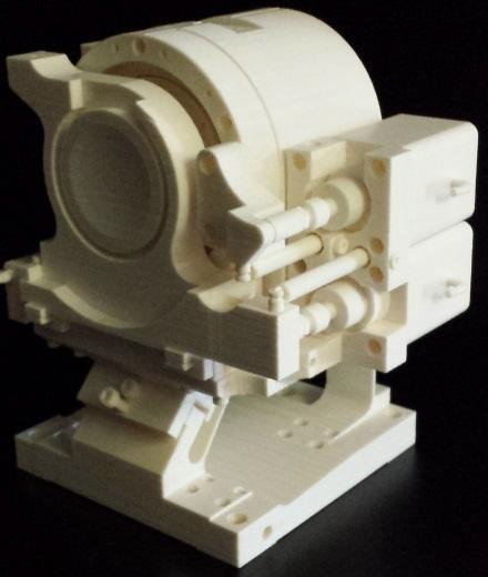
Figure 6. 3D printed Model. Image Credit: Corning Incorporated - Advanced Optics
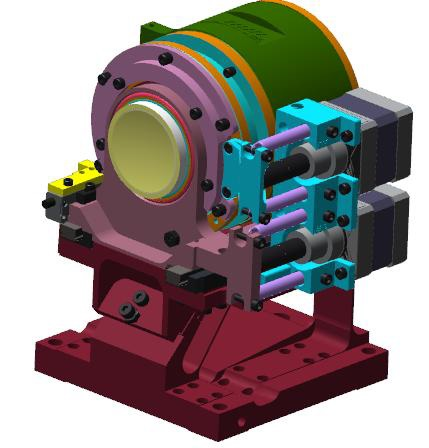
Figure 7. Rendering of final assembly. Image Credit: Corning Incorporated - Advanced Optics
It would have been challenging to dispense and cure the adhesive for doublet 1&2 in the original configuration. This is because the adhesive bondline, which connects the optic to the mechanic, was deep within the mechanical cell barrel.
The dispensing and curing problem was solved by switching to the final configuration. This was likely to ensure a more uniform adhesive application and fuller cure, which heightened the quality of the product.
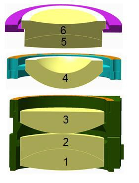
Figure 8. Original Configuration. Image Credit: Corning Incorporated - Advanced Optics
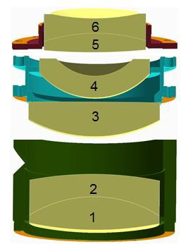
Figure 9. Final Configuration. Image Credit: Corning Incorporated - Advanced Optics
Conclusion
If the customer had chosen to source the objective and tube lens separately, it would have driven the manufacturer of each lens toward more stringent, tighter specifications to ensure performance and compatibility, increasing lead times and costs.
The tube lens example shown here utilizes almost all of the effective manufacturability guidelines outlined earlier. The ability to accomplish this can only be acquired with the atmosphere created by the discipline to use DFM methodology and vertical integration.
Vertical integration can supply benefits like increased quality, shorter lead times, lower cost, and more innovation.
References
[1] Photonics Media, 2018 Photonics Buyers Guide, 2018.
[2] New Wave of Optics and Photonics On Display As 23,000 Registered Researchers, Engineers, Buyers, and Suppliers Converge at SPIE Photonics West 2018. (2017, February 7). Retrieved March 28, 2018, from https://spie.org/about-spie/press-room/press-releases/new-wave-of-optics-and-photonics-on-display-as23000-registered-researchers-engineers-buyers-and-suppliers-converge-at-spie-photonics-west-2018
[3] Buzzell, R.D., “Is Vertical Integration Profitable?”. Harvard Business Review. January 1983.
[4] Anderson, D. M., Design for Manufacturability, Taylor and Francis Group, New York (2014).
Acknowledgments
Produced from materials originally authored by Daniel Staloff from Corning Advanced Optics.

This information has been sourced, reviewed and adapted from materials provided by Corning Incorporated - Advanced Optics.
For more information on this source, please visit Corning Incorporated - Advanced Optics.