For decades, Bragg gratings have been well-known and popular across the world. Optical filtering, interferometers, spectrometers, lasers, waveguiding, optical delay lines and sensors, and dispersion compensators are just a few of the uses. Free-space and waveguide embedded components have both been used to construct Bragg gratings. This article looks at a journal paper titled 'Re-shapeable double-hump Bragg-spectrum using a partial-width entrenched-core waveguide' published in OSA Continuum.
Bragg gratings have been studied in a variety of publications. The high reflectivity of a silicon-on-insulator (SOI) circular Bragg grating mirror across an ultra-broad bandwidth of 500 nm is proven. A multimode one-dimensional photonic crystal waveguide with periodic holes might be used to create a thermally controllable band-stop filter.
To achieve diffraction-free homogeneous waveguide propagation, an SOI long-period subwavelength metamaterial grating is utilized. An SOI micro-spectrometer was built using a circular diffraction grating containing an elliptical concave Bragg mirror.
The numerical demonstration of a unique partial-width entrenched-core (PWEC) waveguide grating utilizing the finite-difference time-domain (FDTD) simulation approach is shown in this paper. A silicon-on-insulator (SOI) planar waveguide compatible with CMOS manufacturing technique is chosen as a few-mode waveguide.
The PWEC is just a series of periodic nano-wide rectangular air-gaps embedded in the center of a core with a width smaller than the core’s diameter. Within the PWEC area, an input infrared TE fundamental mode couples into guided zero and second-order even modes.
The SOI-PWEC is an optical waveguide with a distinctive double-hump (DH) spectrum with two Bragg wavelengths that are closely spaced. The breadth and duration of air trenches are critical in the construction of DH-spectrum features.
They may be adjusted throughout a wide range of shortwave infrared (SWIR) wavelengths (1 to 2 μm). The DH-spectrum properties may be designed by adjusting the width, period, and number of periods in the PWEC trenches.
As a result, the double-hump reflection/transmission spectra can be modified to produce double stop-bands, single wide/narrow pass-bands, notch-bands, or ultra-wide super-bands, for example full mirror.
Methodology
A partial-width entrenched-core waveguide is shown in three dimensions in Figure 1(a). The XY cross-sections of second-order and zero-order electric-field magnitude throughout the grating region are shown in Figures 1(b) and 1(c), respectively.
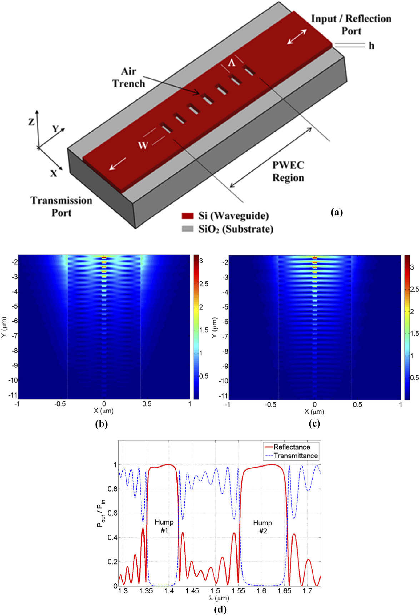
Figure 1. The PWEC waveguide structure and its principle of operation (Λ = 0.32 µm, N = 30, and W = 50 nm). (a) The three-dimensional schematic diagram of silicon-on-insulator partial-width entrenched-core waveguide (PWEC), the duty-cycle is 50%. (b, c) The two-dimensional electric-field magnitudes over PWEC-region for the excited second-order mode (short Bragg-wavelength, λB1=1.386 µm), and the excited zero-order (fundamental) mode (longer Bragg-wavelength, λB2=1.605 µm), respectively. (d) A typical example of double-hump reflection and transmission spectra of PWEC. Image Credit: Awad, 2021
The variational finite-difference time-domain FDTD (2.5D-varFDTD) approach is used to numerically model the PWEC waveguide. When analyzing planar integrated lightwave waveguides, this FDTD approach is equivalent in accuracy to the traditional three-dimensional FDTD method. It offers the advantages of requiring less simulation time and memory.
Results
The impact of detuning the Bragg-grating period (Λ) on the double-hump spectral features is seen in Figure 2. Bragg resonances (λB1 and λB2) may be adjusted over a wide wavelength range (from 1 to 2 μm) by adjusting the Bragg-period, as shown in Figure 2(a).
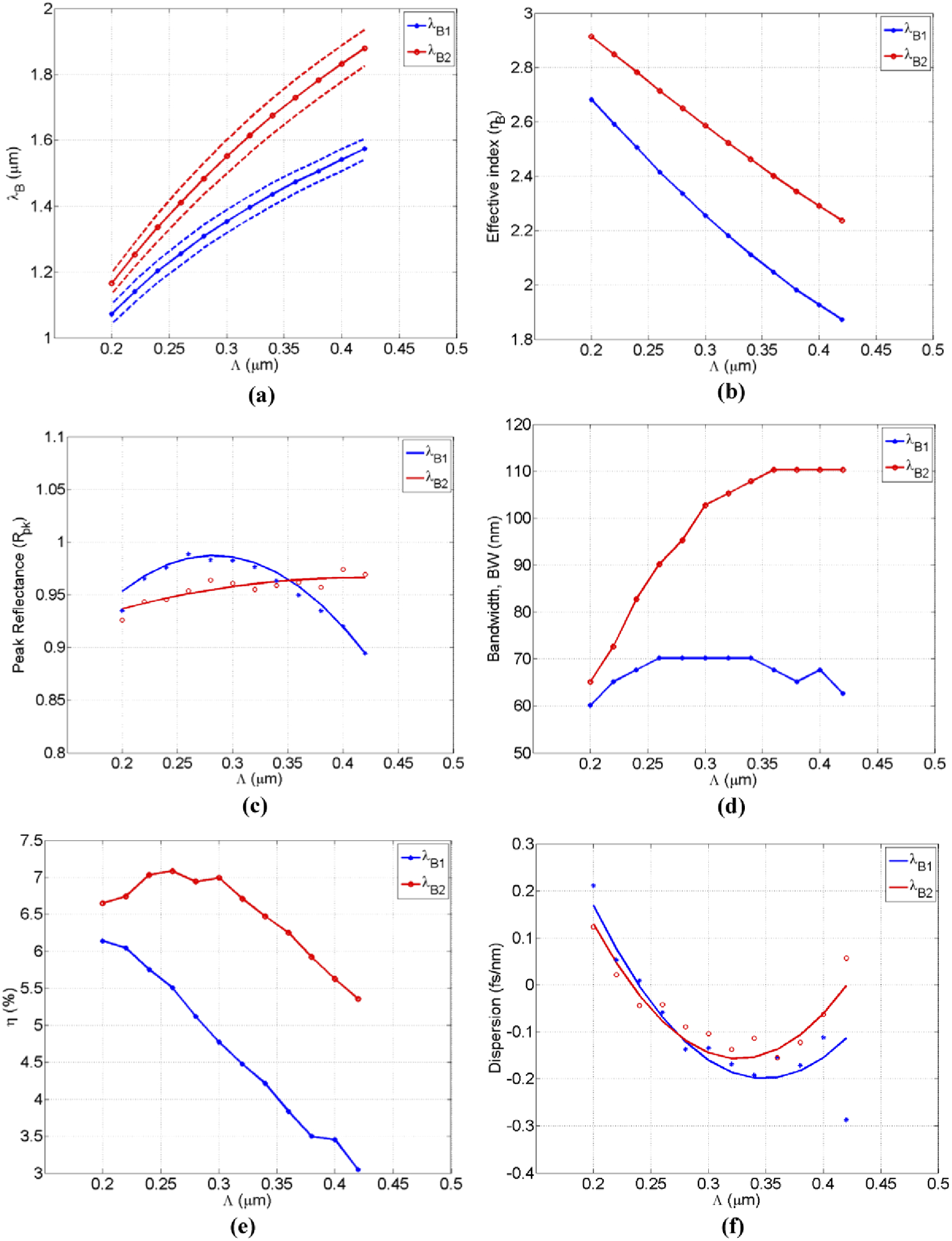
Figure 2. The Characterization of double-hump spectral properties as a function of Bragg-period detuning (W = 50 nm, N = 30): (a) The resonance Bragg-wavelengths tuning. The dashed-lines outline the boundaries of each hump, (b) The effective indices of the two modes, (c) The curve-fitted maximum-reflectance, (d) The humps bandwidths, (e) The coupling overlap-factor between modes, (f) The curve-fitted average dispersion across each reflected hump. Image Credit: Awad, 2021
The effect of detuning the PWEC trench-width (W) on double-hump spectral features is seen in Figure 3. When adjusting the trench-width, Figure 3(a) reveals a wide tuning range of Bragg resonance wavelengths, which is a result of huge variations in effective indices, as seen in Figure 3(b).
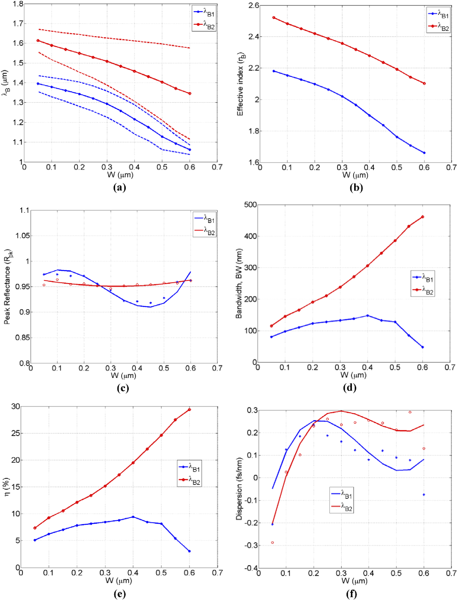
Figure 3. The Characterization of double-hump spectral properties as a function of trench-width (Λ = 0.32 µm, N = 30): (a) The resonance Bragg-wavelengths tuning. The dashed-lines outline the boundaries of each hump, (b) The effective indices of each mode, (c) The curve-fitted maximum-reflectance, (d) The humps bandwidth, (e) The coupling overlap-factor between modes, (f) The curve-fitted average dispersion across each reflected hump. Image Credit: Awad, 2021
Double stop-bands in PWEC’s transmission spectrum correlate to double humps in the reflection spectrum. Figure 4 depicts the reshaped double-hump PWEC spectra. The potential to adjust the DH-spectrum to selectively filter distinct bands within the shortwave infrared (SWIR) area is shown in Figure 4 (a).
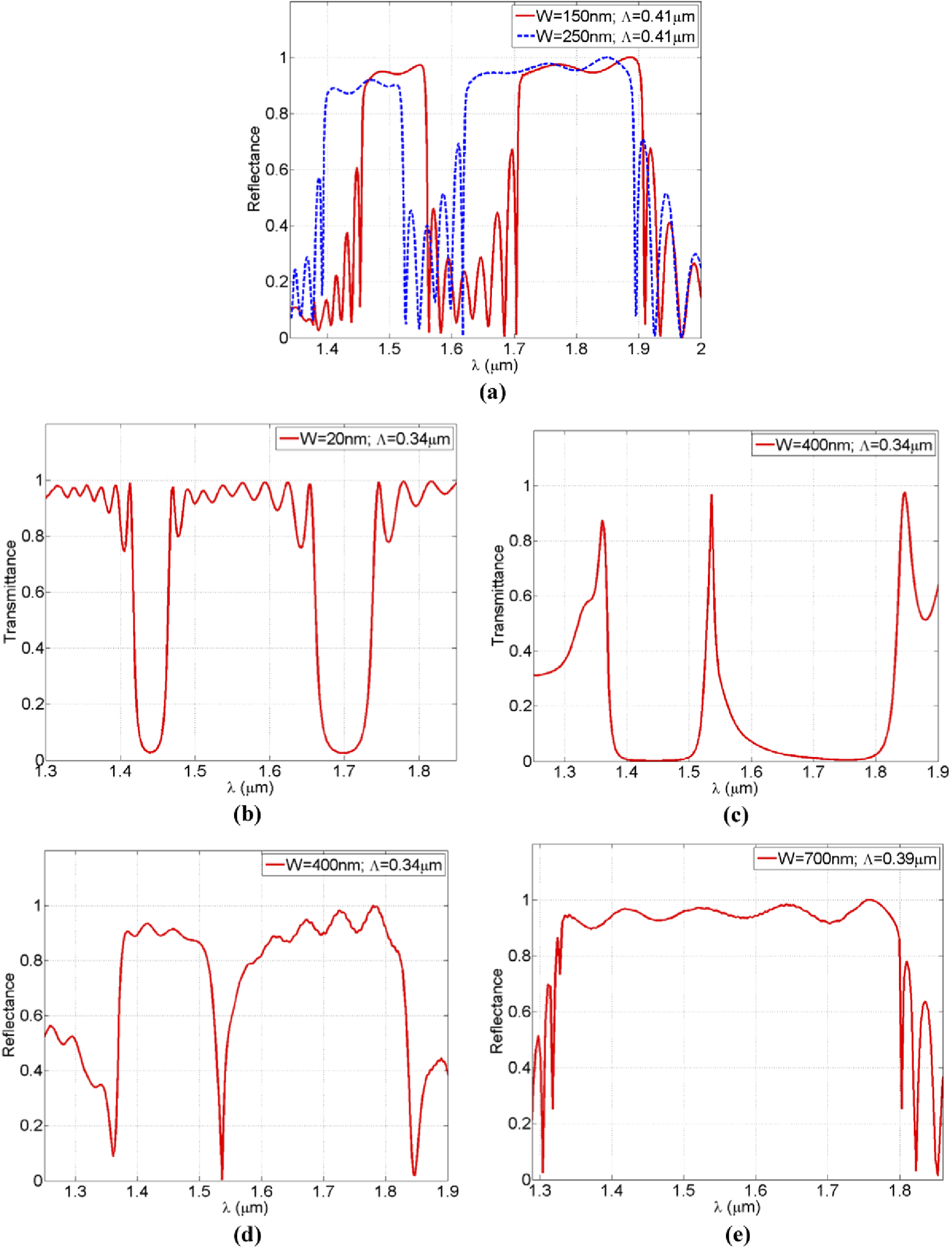
Figure 4. The reshaped double-hump PWEC spectra: (a) The double stop-band spectra covering two of the E, S, C-bands in addition to a part of the SWIR band. (b) A wide pass-band transmission around 1556 nm with a wide bandwidth of 200 nm. (c) A narrow pass-band transmission around 1536 nm with a narrow bandwidth of 10 nm, (d) the notch-reflection spectrum corresponding to pass-band of part (c). (e) An ultra-wide stop-band reflection spectrum around 1565 nm with a bandwidth of 530 nm. Image Credit: Awad, 2021
The PWEC transmission spectrum’s gap between the double stop-bands can be utilized to establish a specific pass-band at the transmission port.
The ultra-wide bandwidth of this super-hump is shown in Figure 4(e) obtained by reducing the effective index below 2, while increasing the coupling overlap-factor above 30%, allowing the bandwidth to reach 450 nm.
Conclusion
A numerical demonstration of a unique partial-width entrenched core (PWEC) waveguide grating is presented in this study. The PWEC displays a double-hump Bragg spectrum with each hump corresponding to one of the waveguide's even modes. The spectrum of this stand-alone few-periods uniform PWEC grating (maximum length is 10.25 μm) may be reconfigured primarily by adjusting the width and period of the air-trenches.
When compared to certain earlier publications, the ultra-wide bandwidth and small size are seen to be advantages.
Journal Reference:
Awad, Ehab (2021) Re-shapeable double-hump Bragg-spectrum using a partial-width entrenched-core waveguide. OSA Continuum, 4(2), pp. 252–261. Available Online: https://www.osapublishing.org/osac/fulltext.cfm?uri=osac-4-2-252&id=446676.
References and Further Reading
- Kashyap, R., et al. (2010) Fiber Bragg Gratings, 2nd ed.
- Saleh, B E A & Teich, M C (2007) Fundamentals of Photonics, 2nd ed. 7.
- Čtyroký, J., et al. (2018) Design of narrowband Bragg spectral filters in subwavelength grating metamaterial waveguides. Optics Express, 26(1), pp. 179–194. doi.org/10.1364/OE.26.000179.
- Giuntoni, I., et al. (2011) WDM multi-channel filter based on sampled gratings in silicon-on-insulator,” Optical Fiber Communication Conference and Exposition and the National Fiber Optic Engineers Conference, pp. 1–3.
- Liu, D., et al. (2020) Four-Channel CWDM (de)Multiplexers Using Cascaded Multimode Waveguide Gratings. IEEE Photonics Technology Letters, 32(4), pp. 192–195. doi.org/10.1109/LPT.2020.2966073.
- Wang, Y., et al. (2017) Ultra-broadband, compact, and high-reflectivity circular Bragg grating mirror based on 220 nm silicon-on-insulator platform,” Optics Express, 25(6), pp. 6653–6663. doi.org/10.1364/OE.25.006653.
- Li, A., et al. (2020) Ultra-compact Bragg grating devices with broadband selectivity,” Optics Letters, 45(3), pp. 644–647. doi.org/10.1364/OL.384688.
- Huang, Q., et al. (2016) Ultra-compact, broadband tunable optical bandstop filters based on a multimode one-dimensional photonic crystal waveguide,” Optics Express, 24(18), pp. 20542–20553. doi.org/10.1364/OE.24.020542.
- Zhao, Y., et al. (2019) Single Wavelength Resonator Based on (Phase-Shifted Antisymmetric Bragg Grating,” IEEE Photonics Technology Letters, 31(16), pp. 1339–1342. doi.org/10.1109/LPT.2019.2927996.
- Chen, L. R., et al. (2019) Subwavelength Grating Waveguide Devices for Telecommunications Applications,” IEEE Journal of Selected Topics in Quantum Electronics, 25(3), pp. 1–11. doi.org/10.1109/JSTQE.2018.2879015.
- Alonso-Ramos, C., et al. (2019) Diffraction-less propagation beyond the sub-wavelength regime: a new type of nanophotonic waveguide,” Scientific Reports, 9(1), p. 5347. doi.org/10.1038/s41598-019-41810-0.
- Zhang, W & Yao, J A (2018) Fully reconfigurable waveguide Bragg grating for programmable photonic signal processing,” Nature Communications, 9(1), p. 1396. doi.org/10.1038/s41467-018-03738-3.
- Pottier, P., et al. (2014) Integrated Microspectrometer with Elliptical Bragg Mirror Enhanced Diffraction Grating on Silicon on Insulator,” ACS Photonics, 1(5), pp. 430–436. doi.org/10.1021/ph400165j.
- Sahin, E., et al. (2019) Bragg Soliton Compression and Fission on CMOS-Compatible Ultra-Silicon-Rich Nitride.” Laser Photonics & Reviews, 13(8), p. 1900114. doi.org/10.1002/lpor.201900114.
- Ansys Lumerical software
- Palik, E D (1997) Handbook of Optical Constants of Solids, (Academic Press, New York).