In a new interview, AZoOptics talks with Professors Susmu Noda and Menaka De Zoysa about their research presenting a new nonmechanical 3D Lidar system.
Please could you introduce yourself and your professional background?
 Susumu Noda received his B.S., M.S., and Ph.D. degrees from Kyoto University, Kyoto, Japan, in 1982, 1984, and 1991, respectively, all in electronics, and received an Honorary degree from Gent University, Gent, Belgium, in 2006. From 1984 to 1988, he was with the Mitsubishi Electric Corporation. He joined Kyoto University in 1988, where he is currently a Professor in the Department of Electronic Science and Engineering and the Director of the Photonics and Electronics Science and Engineering Center. He is a Fellow of the Japan Society of Applied Physics and IEEE. His research interests include physics and applications of photonic nanostructures based on photonic crystals.
 Menaka De Zoysa received his B.S., M.S. and Ph.D. degrees in Electronic Science and Engineering from Kyoto University, Kyoto, Japan, in 2007, 2009 and 2012 respectively. From 2010 to 2012, he was a Research Fellow of the Japan Society for the Promotion of Science at Kyoto University. From 2012 to 2014, he was a Post-doctoral fellow in the Quantum Optoelectronics Laboratory. From 2014 to 2016, he was an Assistant Professor at the Hakubi Center for Advanced Research, Kyoto University. He is currently a Senior Lecturer at Photonics and Electronics Science and Engineering Center, Kyoto University. His research interests include development and improvement of photonic crystal lasers, and thermal emission control based on manipulation of electronic and photonic states.
What is Lidar and how is it used?
Lidar, which is an acronym for “Light detection and ranging,” is a method for determining the distances of objects by measuring the time taken for light emitted from a laser to be reflected from these objects and returned to a detector. The core components of a LiDAR system are (1) a laser light source, whose laser beam can be emitted or scanned over a broad, two-dimensional field of view (FoV); (2) a detector, which detects the laser light that is reflected by and returns from objects; and (3) control electronics for operating the laser and the detector and for calculating the laser beam’s time of flight (ToF) from the laser to the detector.
Unlike a conventional camera, which can determine only the positions of objects in a 2D plane, a LiDAR system can capture a fully three-dimensional (3D) image, which involves not only the positions of objects but also their distances. In this capacity, LiDAR systems are expected to be widely applied as “eyes” in many areas of our future society, including “smart” mobility, where capturing fully 3D images will be vital for safe, autonomous motion of robots, vehicles, and farming and construction machinery.
What is the difference between conventional Lidar and Flash Lidar?
At present, most LiDAR systems under development are mechanical beam-scanning-type ones. To scan the beam, these systems rely on moving parts, such as motors, which make the systems bulky, expensive, and unreliable. To overcome such issues, it is very important to develop non-mechanical LiDAR systems.
One type of non-mechanical LiDAR system, known as flash LiDAR (see Fig.R1), simultaneously illuminates and evaluates the distances of all objects in the FoV with a broad, diffuse beam of light, allowing for a fully 3D image to be obtained in a flash. However, these systems have the critical drawback of being unable to measure the distances of poorly reflective objects like black metallic cars due to the very small amount of light reflected from these objects. In addition, external optical elements, such as lenses and diffractive optical elements, are required to obtain the flash beam, which make the system very large and thus give rise to another critical drawback.
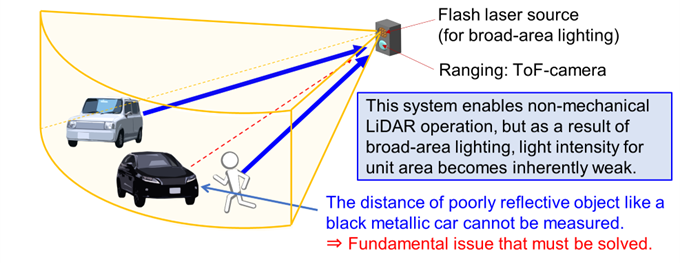
Fig. R1: Conventional flash LiDAR system consisting of a flash laser source and a (time-of-flight, or ToF) camera for measuring distance. This system struggles to measure poorly reflective objects in the field of view due the small amount of light reflected from these objects.
In your latest paper, you presented a new nonmechanical 3D Lidar system. Could you describe the research and development process for this technology?
Both conventional (i.e., mechanical beam-scanning) Lidar and flash Lidar are beset by critical drawbacks which make the overall systems bulky, expensive, and/or unreliable. To address these drawbacks, we developed a unique type of light source, which we call a “dually-modulated photonic-crystal surface-emitting laser (DM-PCSEL).” With this light source, we can achieve not only flash illumination, but also electronically controlled, 2D beam-scanning illumination – that is, the scanning of a more concentrated laser beam – without relying on any of the bulky moving parts nor bulky external optical elements that encumber the beam-scanning and flash LiDAR systems. This unique light source allowed us to create a conceptually new and compact Lidar system that marries the individual advantages of beam-scanning Lidar and flash Lidar without being bottlenecked by their individual drawbacks.
The basic concept of this DM-PCSEL-based Lidar system is outlined in Fig. R2. As illustrated in this figure, the Lidar system measures the distances of many objects all at once by wide flash illumination while also selectively illuminating poorly reflective objects with a more concentrated beam of light when such objects are detected in the ToF camera image. Furthermore, by using a combination of software and electronic control, the Lidar system can even automatically track the motion of the poorly reflective objects by beam-scanning illumination. In this way, this Lidar system can range not only highly reflective objects, but also poorly reflective ones simultaneously. We believe that this Lidar system will help realize smart mobility in the nascent era of Society 5.0, a future “smart” society envisioned by the government of Japan [1].
Our research has been conducted under the Japanese national projects “CREST” (Core Research for Evolutional Science and Technology) and “SIP” (Cross-ministerial Strategic Innovation Promotion Program) for photonics and quantum technology for Society 5.0, which were launched to support the realization of Society 5.0.
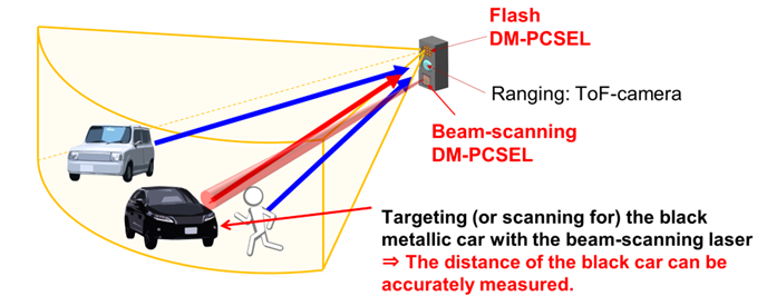
Fig. R2: Proposed new LiDAR system combining dually-modulated surface-emitting photonic-crystal laser (DM-PCSEL)-based flash and beam-scanning light sources. Two-dimensional beam-scanning is used to selectively illuminate and measure the distances of the poorly reflective objects. In addition, introducing pattern recognition in the LiDAR system enables automated distance measurements of the poorly reflective objects.
What is a dually modulated photonic-crystal laser, and how did you employ it here?
A dually modulated photonic-crystal laser surface-emitting laser (DM-PCSEL) is a type of semiconductor laser in which light oscillates inside of a special type of resonator called a photonic crystal. With this photonic crystal, the light can oscillate coherently over a broad area and can also be emitted from the surface of the crystal, resulting in the emission of a powerful and narrowly diverging (i.e., “high-brightness”) laser beam. In a DM-PCSEL, the positions and the sizes of the lattice points (i.e., air holes) comprising this photonic crystal are simultaneously tuned, or “dually modulated,” in order to tailor the properties of the emitted beam, such as its emission angle with respect to the surface and its divergence angle.
Here, we developed two types of DM-PCSELs; one was tailored to emit a broad beam of light for flash illumination, and the other was tailored to emit concentrated beams of light at one hundred unique emission angles for selective, beam-scanning illumination. We loaded both of these light sources into a single 3D LiDAR system so that we could measure the distances of many objects all at once by wide flash illumination while also selectively measuring the distance of poorly reflective objects with beam-scanning illumination when such objects are detected in a camera image (see Fig. R2). Furthermore, by using a combination of software and electronic control, we could even automatically track the motion of poorly reflective objects by beam-scanning illumination.
A photograph of our 3D LiDAR system, containing both flash and beam-scanning DM-PCSELs, is shown in Fig. R3. As shown in this figure, the DM-PCSEL flash source could illuminate a wide 30o×30o FoV, and the DM-PCSEL beam-scanning source could illuminate small spots with a selection of one hundred narrow laser beams (where the divergence angle of a single beam was less than 1o). ToF distance measurements were performed using the ToF camera installed toward the bottom of the system. These lasers, the ToF camera, and all associated components required to operate the system were assembled in a compact manner, resulting in a total system footprint that was smaller than that of a business card.
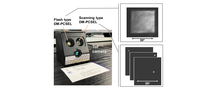
Fig. R3: Photograph of the developed 3D LiDAR system implementing dually-modulated surface-emitting photonic-crystal laser (DM-PCSEL) -based flash and beam-scanning light sources. A business card is placed in front of the system for perspective.
To provide a clearer sense of our developed 3D LiDAR system in action, allow us to consider the following practical scenarios: First, suppose that a highly reflective white object and two poorly reflective black objects exist simultaneously in the field of view of the camera, as shown in the black-and-white image of Fig. R4a. If we attempt to measure the distances of these objects using only the flash laser source, we can only measure the distance of the white object, as shown in the distance image of Fig. R4b; the black objects cannot be measured due to the small amount of light that is reflected from these objects. However, we can recognize the presence of these black objects by simply looking at the black-and-white image (Fig. R4a). So, we turn on the beam-scanning laser source and illuminate these objects with beams of light that are more concentrated than that of the flash laser source. By doing so, a sufficient amount of light is reflected from these objects, enabling the measurement of their distances, as shown in the Fig. R4c. We will provide a video demonstrating this distance measurement (Ranging_poorly_reflective_objects.mp4).
Second, in a dynamic, real-world scenario, it is quite likely that these black objects will have places to be, and thus they will be in motion. In order to keep track of their motion in real time, we employ our developed software program and electronic control, which allows us to automatically recognize the poorly reflective objects and measure their distances by selective illumination. We will also provide a video demonstrating such automated detection and motion tracking (Full_automatated_ranging_poorly_reflective_objects.mp4).
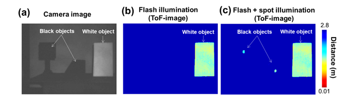
Fig. R4 (a): Camera image of one highly reflective white object and two poorly reflective black objects for distance measurement. (b): Distance measurements obtained by the LiDAR system using only the flash laser source; the distances of the black objects cannot be measured. (c): Distance measurements obtained by the LiDAR system using both flash and beam-scanning laser sources; the distances of both black and white objects can be measured simultaneously.
How is this system able to function better than previous technologies?
Our developed system is a completely new approach that unifies the advantages of broad flash illumination and concentrated beam-scanning illumination. This combination makes our system uniquely capable of measuring the distances of both highly reflective objects and poorly reflective objects in the same FoV. Such a capability is vital when applying Lidar to real-world settings, which are littered with objects of all sorts of colors and reflectivities.
Furthermore, by virtue of its DM-PCSELs, our developed system can achieve flash illumination and beam-scanning illumination over a 2D FoV of arbitrary size, without relying on any additional, external, bulky optical elements, such as lenses and diffractive optical elements, nor any mechanical moving parts. These lasers, together with the technology behind the electronics used to operate them and the other control electronics, allow us to improve the reliability of the overall system, as well as reduce its complexity, cost, and size.
What are some of the practical applications of this Lidar system?
Our new LiDAR system can be applied to smart mobility, such as the autonomous movement of robots, vehicles, and farming and construction machinery for Society 5.0. With this system, such robots, vehicles, and machinery will be able to reliably and safely navigate a dynamically changing environment without losing sight of poorly reflective objects, which is essential for safe autonomous driving without accidents.
What is the most exciting or significant aspect of this research to you?
We believe the most significant aspect of our work is the unique and important capabilities of our developed DM-PCSELs. It is unusual for a light source to attain the high-level functionalities of flash illumination and 2D beam-scanning illumination without the use of external optical elements and/or mechanical moving parts. (In fact, although this has not been the focus of the present work, DM-PCSELs can be tailored to emit various other beam patterns, such as multiple dots for face recognition and even detailed images of logos and artwork.) These capabilities are what has enabled us to unify the individual merits of both flash and beam-scanning LiDAR systems and thus overcome the critical drawbacks that have affected conventional systems.
What are the next steps?
The next step for us is to demonstrate a practical application of our DM-PCSEL-based LiDAR system, such as the autonomous movement of robots and vehicles, in a real-world setting. Such demonstrations will be relatively straightforward, since all of the necessary components and control units are already compactly integrated in the system and the necessary software is already implemented. In the future, we are also considering to replace the ToF camera of our LiDAR system with a more optically sensitive single-photon avalanche photodiode array to measure objects across even longer distances. From there on, we expect our DM-PCSEL technology to lead to the realization of on-chip, all-solid-state 3D LiDAR.
Where can readers find more information?
[1] https://www8.cao.go.jp/cstp/english/society5_0/index.html
Link to original Optica paper: https://opg.optica.org/optica/fulltext.cfm?uri=optica-10-2-264&id=525949
Full_automatated_ranging_poorly_reflective_objects.mp4
This video demonstrates the ability of our LiDAR system to measure the distance of poorly reflective objects. When using only the flash laser source, the distances of the poorly reflective objects cannot be measured, although the highly reflective object can be measured. However, by operating the beam-scanning laser source, the distances of black objects can be successfully measured.
Ranging_poorly_reflective_objects.mp4
This video demonstrates real-time 3D sensing using the developed and fully-automated LiDAR system. Automated distance measurements of a black object (moved by hand) are carried out by detecting the position of this object from the camera image and then selectively illuminating this object by the beam-scanning laser source.
We courteously invite readers to visit the website of the Center of Excellence (COE) for Photonic-crystal Surface-emitting Laser (PCSEL). This website provides more information about the technology and development history of PCSELs, as well as our contact information. https://pcsel-coe.kuee.kyoto-u.ac.jp/
Disclaimer: The views expressed here are those of the interviewee and do not necessarily represent the views of AZoM.com Limited (T/A) AZoNetwork, the owner and operator of this website. This disclaimer forms part of the Terms and Conditions of use of this website.