Mirrors are components found throughout optical systems. They can be utilized to focus and steer light, reject particular wavelengths, and combine wavelengths in imaging and additional applications. Several factors should be considered when selecting a mirror.
Materials
Metallic Mirrors provide a combination of absorbance and reflectance (and transmittance if adequately thin).
They can be employed as neutral density filters, neutral beamsplitters, or wide wavelength-range reflectors. The kind of metal utilized defines its spectral features. The application of these mirrors is mostly outside of angle-of-incidence.
Dielectric Mirrors comprise of delicate layers of non-absorbing materials (normally fluorides and oxides), which vary in refractive index. The composition and thickness of the layers are configured to create reflectance or transmittance in wavelength ranges specified by the application or customer.
These materials absorb little to no light, so dielectric mirrors can frequently be employed as dichroic mirrors (where light of certain colors travels through while reflecting the light of different). Both the angle-of-incidence and the wavelength range must be determined at the design stage.
Function
Imaging - Needs a flatness of λ/10 or better to reduce image distortion. Beam-steering, non-imaging applications do not demand strict specifications on flatness.
Wavelength combining - Dielectric dichroic mirrors are utilized to bring together different laser beams onto one axis. This application requires a flatness of 1/4λ per inch or more.
Wavelength splitting - Desired wavelengths can also be reflected with the use of dielectric dichroic mirrors. Applications involve hot-mirrors that exclude IR and NIR light, transmitting emission light, and reflecting excitation light while identifying alternate wavelength bands with several detectors.
The reflecting and transmitting wavelengths must be thoroughly defined for this kind of application. These are normally utilized at a 45° angle of incidence.
Wavelength rejection - A researcher may want to exclude particular wavelengths from the system in some cases.
Some examples are order-sorting filters (where undesired wavelengths are reflected), cold mirrors (where shorter wavelengths are reflected while longer wavelengths are transmitted, often used in lamp assemblies), and hot mirrors (which reflect IR or NIR).
From a functional perspective, these are dichroic mirrors which are applied in a different respect. They are normally used at near-normal to normal incidence.
Angle of Incidence
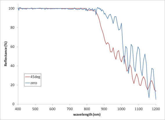
Mirrors are mostly configured to be employed at a particular angle of incidence. Hot mirrors are normally utilized at zero or near zero degrees AOI, whereas dichroic mirrors are frequently used at 45°.
The AOI is determined by the optical design of the system. Differences in polarization should be explored when the AOI is more than around 25°. Read the article on angles of incidence to gain more information.
Physical Environment
The requirements for durability should be established according to the physical environment of which the mirror will be exposed.
Temperature cycling is critical for space applications. For applications in the outdoors, temperature and humidity cycling, abrasion resistance, condensation, and salt fog may be considerations.
Radiative flux (when the filter is put into a highly energetic or intense beam) may lead to a decline in performance over time. There are limited environmental requirements in air-conditioned laboratory spaces or a protected laboratory instrument.
Wavelength Range
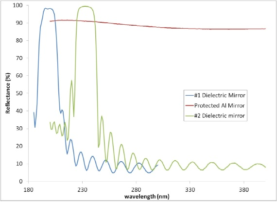
UV (180-400 nm) While conventional metal mirrors perform across a wide range of wavelengths, other metals may work better over particular wavelength ranges. First-surface aluminum mirrors protected with Magnesium Fluoride are normally suggested below 430 nm.
Omega has additionally produced dielectric mirrors tailored to this range that comprise of delicate layers of transition metal oxides or silicon dioxide, magnesium fluoride, and lanthanide fluorides for the lower wavelengths.
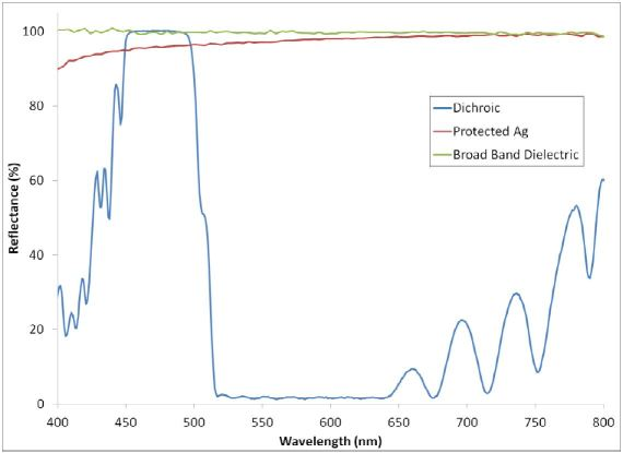
Visible (400-700 nm) Visible mirrors are traditionally made from silver on the top side (the first-surface) or the backside of a piece of glass. They are frequently shielded with an extra layer of silicon dioxide (for the first-surface) or a plastic material that is not transmissive (for the back surface).
Dielectric mirrors comprise of non-absorbing materials in alternating layers and are produced to enhance reflectance at particular wavelengths and angles while excluding others. Enhanced metal mirrors use both dielectric and metal layers to optimize reflectivity.
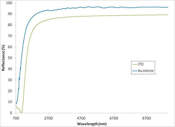
NIR – IR (700 nm - 10 micron) In the IR and NIR, gold mirrors are commonly employed, which absorb light in certain visible wavelengths but also contain a high reflectance (greater than 95% above 1,500 nm).
A different choice is a transparent conductive oxide mirror (such as ITO) which offers transparency at shorter (visible) wavelengths with high reflectivity at longer wavelengths.
Broadband An application may sometimes need high reflectivity across a wavelength range that covers many of those mentioned earlier. These applications are astronomy, solar photothermal or photovoltaics, and hyperspectral imaging.
For the flattest and highest reflectivity response, dielectric mirrors can be produced (the same as the Ultra Broadband Dielectric Mirror).
This information has been sourced, reviewed and adapted from materials provided by Omega Optical, Inc.
For more information on this source, please visit Omega Optical, Inc.