Interference filters are widely used in transmissive configurations where the light travels through the filter to create a particular effect (short-pass, band-pass, long-pass, and more).
These filters can additionally be employed in a reflective configuration where the wanted light is reflected using the filter, and the transmitted light is absorbed or rejected.
Interference filters do not normally absorb any light; all of the light is transmitted or reflected (as shown in Figure 1). There are some exceptions, particularly in UV and IR, where the inherent characteristics of the materials result in the absorption of specific wavelengths. In the majority of thin films, scatter also occurs at a small level.
Applications like beam combining and fluorescence exploit this ability to reflect certain wavelengths while transmitting others.
Beam combining is where laser beams of various wavelengths are focused onto a single optical axis. Fluorescence applications use dichroic mirrors to transmit fluorescence signals and reflect excitation wavelengths.
The total of the transmitted and reflected light is 100% when no absorption is occurring.
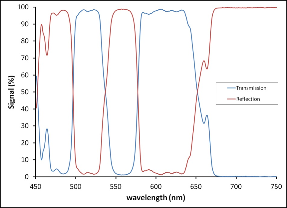
Figure 1. %T and %R of a filter at a 45° angle of incidence. These add up to 100% for most interference filters in the visible wavelength regime.
Baffle Filters - A reflective filter assembly is called a ‘baffle filter’ by Omega, which is where several reflecting filters are placed to create the intended effect. A range of configurations can be planned to stabilize the optical axis or direct the beam in a specific direction (shown in Figure 2).
As an alternative, the separate filters can be employed as folding or steering mirrors in the optical system design of the customer.
One element to consider is that the filter will have the most effective performance (highest reflection or transmission and steepest edges) in a collimated beam at a single angle of incidence (AOI). Normally, splitting of s and p polarization happens at greater AOIs, but some of this is controllable at the design stage of the filter.
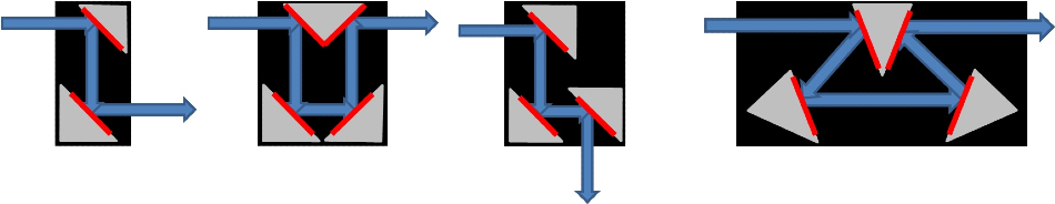
Figure 2. Some Baffle Filter designs at 45° and 22.5° AOI. These design concepts can be incorporated into nearly any optical system.
Applications and Performance
UV band-pass filters with visible light blocking - The majority of materials employed for thin-film coating begin by absorbing light in the UV (less than 350 nm or so). This absorption makes it highly complex to create a strongly transmitting UV filter while blocking the complete visible spectrum at the same time.
The conventional technique is the use of induced transparency in metals (MDM design) to attain strong visible blocking and a certain level of transmission in the UV (see Figure 3). This category of filter normally has a low transmission rate (less than 50%), but a high blocking level.
Steeper edges and higher transmission can be attained with purely dielectric stacks (Figure 3) of materials that are UV-compatible, but the blocking range is restricted unless very big stacks are employed.
Changing to a reflecting (baffle box) arrangement with a 22.5° AOI enables a high %T in the band-pass and effective blocking in the visible as a result of the use of absorbing epoxies in the assembly.
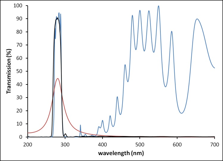
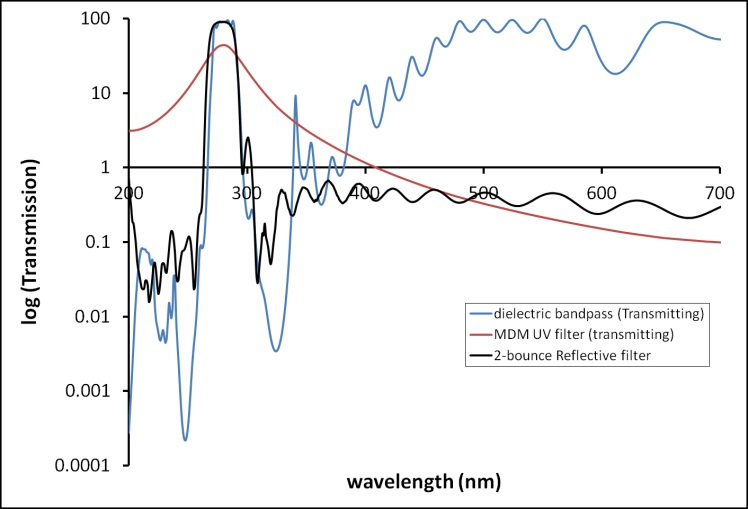
Figure 3. Comparison of MDM and transmissive UV filters with a 2- bounce reflective filter. Top: linear scale, Bottom: log scale to emphasize blocking. The reflective filter maintains narrow bandwidth, high throughput, and blocking over a wide wavelength range.
Narrow notch rejection filters - Transmissive notch filter designs are very challenging due to the nature of thin-film interference filters, particularly when a high OD is necessary over a very narrow wavelength.
Omega is experienced in creating extremely high transmitting narrow band-pass filters, which, when utilized in reflection, can produce narrow notches.
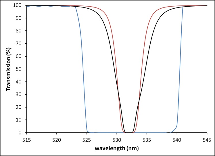
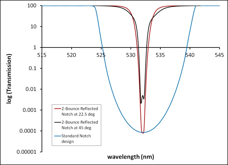
Figure 4. Top: A standard transmissive notch design with 2-bounce reflective notches designed at 2 AOIs. Bottom: The same data presented in log scale to show blocking (OD 6 in red and blue curves).
Using this method of design, the width of the notch at 50% T can be decreased from around 16.5 nm (in the average transmission filter) to 6.2 nm wide at 45° and 4.3 wide at 22.5° AOI.
Maximizing the AOI widens the notch due to the splitting of the two states of polarization (s and p) at an angle. This process can be observed in the bottom of Figure 4 as a double-dip in the black trace.
Omega assists its customers in ‘thinking inside the box’ with their ongoing optical design projects. Please get in touch with Omega to discuss how baffle filters and these design principles can be incorporated into any system.

This information has been sourced, reviewed and adapted from materials provided by Omega Optical, Inc.
For more information on this source, please visit Omega Optical, Inc.