
Richard Austin, President of Gamma Scientific, speaks to AZoOptics about Night Vision equipment, the importance of equipment testing standards and why the measurement systems provided by Gamma Scientific are the most accurate way of adhering to them.
Can you please provide a brief introduction to Gamma Scientific?
Gamma Scientific was founded in 1961 and has been providing precision optical radiation sources and measurement equipment to the Aerospace, defence, display and lighting, R&D and manufacturing and medical industries, as well as retroreflective highway safety materials and lighting for worldwide National Standards laboratories.
In the early to mid-1980s, spectroradiometer systems were used to determine the appropriate light levels emitted from aircraft cockpit displays to allow safe flight operations by pilots outfitted with Night Vision goggles.
How do NVIS products work?
“NVIS products” is a broad category that refers to Night Vision Imaging System components that encompass the actual Night Vision Goggles worn by pilots and other motorized vehicle operators to lighting components as well as assemblies used on the exterior and interior of aircraft and vehicles.
Gamma Scientific is involved in the manufacturing of instrumentation used to verify compatibility between Night Vision Goggles and vehicle lighting components.
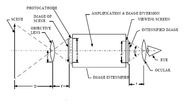
A schematic diagram showing how night vision goggles achieve the amplifcation of radiation from a night-time scene
The picture above shows how the current generation of night vision goggles works. There is an object or ‘scene’ on the left hand side. An objective lens results in formation an image on the outside surface of the goggles which acts as a photocathode.
The photocathode converts light into electrons, which can then be amplified to give a signal. The signal is then displayed as an image on a phosphor screen on the other size of the goggles. An ocular is used to allow the eye to focus on the intensified image on the phosphor screen.
Military vehicles, law enforcement and rescue helicopter pilots all use these devices to improve their vision in low light conditions, and they are becoming more ubiquitous.
How can this cause an incompatibility problem when used in low light in a cockpit?
Night vision goggles (NVG’s) have their greatest sensitivity in the near infrared portion of the spectrum, which is where moonlight and starlight energy is concentrated. This allows the NVG user to see images under conditions where the human eye cannot.
However, too much near IR light in the aircraft cockpit activates an automatic gain function in the goggles reducing or completely eliminating the goggles sensitivity to the low light conditions making exterior landscape and topography details invisible; essentially blinding the pilot to what is outside the cockpit.
For that reason, attention must be paid to IR radiation from light sources that will be active whilst NVG’s are in use. Unless sources of IR radiation are eliminated the NVG’s will be incompatible with the safe operation of the aircraft.
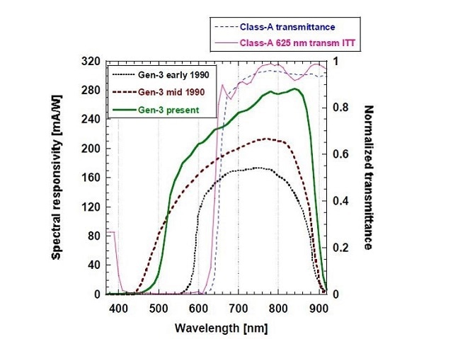
A graph showing the sensitivities (in terms of wavelength) of the photocathodes in different generations of night vision goggles from 1970 to present
The wavelength range over which NVG’s are sensitive vary, with ranges that start from around 400 to 930 nm, and with the visible blocking filter on there is a lot of energy conversion between 615 to 900 nm.
In the early 1980s, when these high sensitivity goggles were introduced into cockpits, the near infrared energy from the small tungsten lamps used to illuminate cockpit displays and switch panels were found to affect the performance of the goggles. This prompted the need for a definition of allowable IR radiance to ensure NVG compatibility.
What does the MIL-L-85762A specification for Night Vision Imaging Systems outline and why is it important?
The document, when drafted in the early 1980s, established how much emission of light from the near IR portion of the spectrum (where Aviator’s Night Vision Imagining System (ANVIS) Goggles have their greatest sensitivity) can be allowed and still not adversely affect their ability to safely pilot the aircraft.
When the scientific basis for the definition of these light levels was being discovered, Gamma Scientific was part of EG&G, and at the time we were the leading manufacturer of computer controlled spectroradiometer systems using high sensitivity Photomultiplier tubes (PMTs) for many different market areas, the largest being display color and luminance measurements.
Our Model C-9 and later C-11 spectroradiometer equipment was used to determine what light levels existed in the outdoor night-time environment. From these measurements, the appropriate near infrared light levels required to prevent interference with the goggle sensitivity were determined. These levels were then used to create maximum allowable infrared radiance values and were incorporated into the new MIL-L-85762 standard.
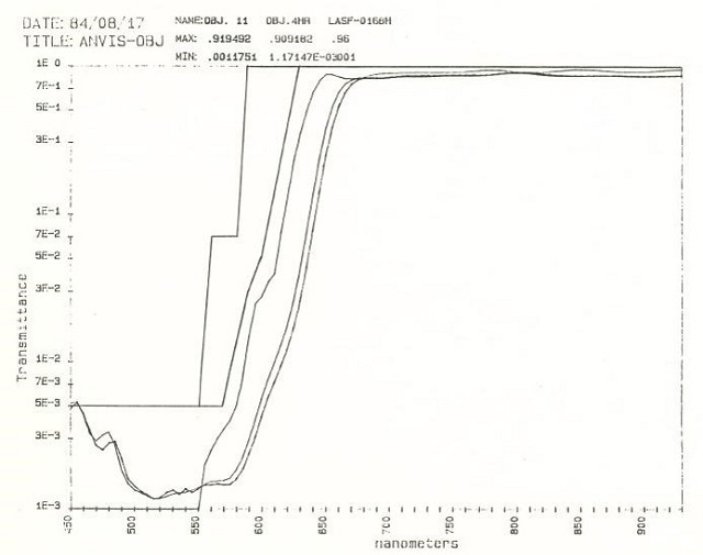
A graph showing the spectral sensitivity measurements of different NVGs achieved using a Model C-9 spectroradiometer
The above graph, from August 17, 1984, shows the spectral sensitivity curves of goggles acquired using our Model C-9 spectroradiometer configured as a monochromatic source. This goggle performance data was used to define the weighting functions used to calculate NVIS Radiance levels as required by MIL-L-85762.
The NVIS radiance calculation provides an indication of the amount of interfering radiation that would affect the sensitivities of the goggles. These functions are still used in the current MIL-STD-3009 that replaced MIL-L-85762A from the original MIL-L-85762. The process for determining the level of NVIS radiance is to make a spectral radiance measurement and then apply these weighting functions to the measured spectral data.
The area under the combination of these curves, given by computing the integral, shows how much energy from the cockpit lighting would be “seen” by the NVG. So, the crux of the standard is establishing a quantitative means to ensure that low enough light levels from ambient cockpit lighting are maintained to allow the goggles to operate properly. If there is too much light, the ability of the goggles to amplify light from the outside is degraded, meaning the pilot essentially becomes blind to what is outside the cockpit.
As you can see, Gamma Scientific has been involved in the generation of Night Vision Goggle compatibility standards from the very beginning.
What considerations should potential customers take into account when looking to purchase NVIS measurement equipment?
It comes down to the accuracy of the measurement. Customers must be able to rely on the measurement results produced by their NVIS measurement system. Inaccuracies in measured data can be very costly. An NVIS measurement system that erroneously reports high NVIS radiance levels can force a customer to over-engineer their lighting product.
Conversely, a system that reports inaccurately low NVIS radiance levels can create problems when the product is integrated into the cockpit system, when it is often too late to address the problem. False failure reports are often caused by inadequate sensitivity or poor spectral purity.
NVIS radiance measurements are one of the most difficult lighting measurements to make. NVG’s are highly sensitive because they must amplify the limited light available in typical night time scenes, so it is critical that the NVIS radiance from lighting sources in the environment are lower than the night scene levels.
To measure these low radiance levels, NVIS measurement equipment must be even more sensitive than the NVG’s in order to report accurate radiance levels. The measurement equipment must also exhibit high levels of spectral purity because the weighting functions defined in the MIL standard are wavelength dependent and the weighting values change rapidly from the visible to near IR regions.
Trying to select an NVIS measurement system based solely on data sheet specifications can be misleading, if the measurement system supplier is not capable of producing consistent quality. The experience of the company that's providing the measurement equipment is important to consider, as is third-party accreditation to laboratory standards like ISO/IEC 17025 .
What equipment is offered by Gamma Scientific to perform NVIS measurements?
We offer the following equipment:
GS-1290-NVIS Spectroradiometers that measure lighted components used in and on aircraft to test compliance with the requirements in MIL-L-85762A and MIL-STD-3009.
RS-5NVIS Tunable Light Source (TLS) systems that provide a match to the spectral irradiance for night time illumination conditions from new moon/starlight to full moon conditions.
TIA-3000 Primary standard radiometers used to provide low uncertainty calibration and correlation of night vision goggle test sets. These are used by the US national standards laboratory and the military branches standards laboratories.
How does the GS-1290-NVIS system compare to other NVIS measurement solutions on the market?
We have repeatedly demonstrated the superior spectral purity and sensitivity of our GS-1290-NVIS system through head to head comparison testing that involved the leading suppliers of NVIS measurement equipment.
In virtually every case, our GS-1290-NVIS system has performed better than competing CCD array spectroradiometer systems. In fact, the performance of our product compares well to older generation scanning, double grating spectroradiometers like our C-11 PMT-based spectroradiometer. While we no longer sell the C-11 system, due to its high cost and slow speed of operation, it still serves as our in-house laboratory standard because of its accuracy.
Recently, we took on a challenge with a leading LCD panel manufacturer that produces a specialized, retrofit display for use in aging military aircraft. This manufacturer has been doing quality control testing for years using an old, scanning, single-grating PMT-based spectroradiometer, but that system became obsolete a few years ago and is no longer supported. So they have a real need for a current-generation NVIS measurement system and they have been evaluating CCD array spectroradiometers as a potential replacement quality control test solution.
When we got involved the LCD manufacturer explained that they had so far been unsuccessful in identifying a CCD based system that could match the performance of the obsolete PMT systems. All of the CCD systems that they tested reported higher NVIS radiance levels than the obsolete PMT systems in use.
Initially, the GS-1290-NVIS system also reported higher NVIS radiance than the PMT system. However, after extensive testing and analysis of our design we were able to achieve comparable performance to the PMT system, by implementing design improvements that lowered the system noise floor, expanded the dynamic range of the system and improved our spectral purity.
We first characterized the LCD panel on our C-11 scanning double grating spectroradiometer system, which serves as our reference standard, and compared it to the customer’s PMT measurement data. The results are shown in the graph below.
The RED plot is our customer’s PMT system data. The black curve is data from the reference standard C-11 system. The area between the red curve and the black curve represent errors in the PMT system.
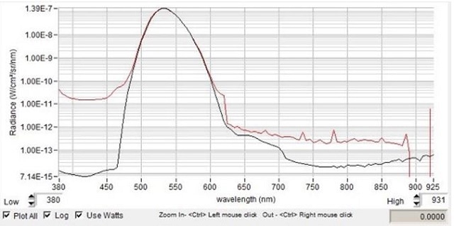
A graph showing a customers PMT system data (red) against data from the reference standard C-11 system (black). The area between the red and black curves represents errors in the PMT system
After implementing design improvements in our GS-1290-NVIS system we were ultimately able to produce spectral plots that matched the customer’s PMT data quite closely.
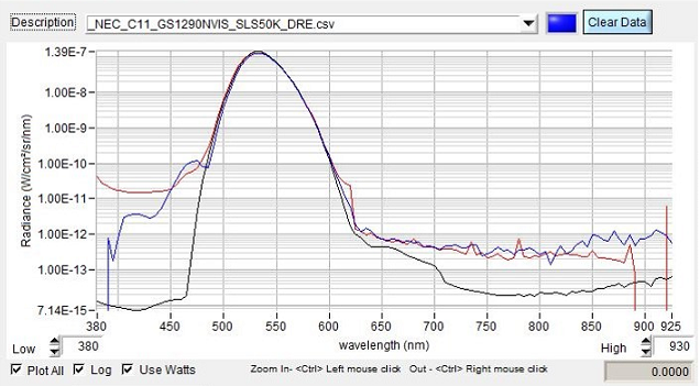
A graph showing Gamma Scientific's GS-1290-NVIS system measurement data (blue) against a customer’s PMT system data (red), and C-11 data (black)
As seen in the graph, the GS-1290-NVIS system was able to match the noise floor of the PMT system.
What features contribute to NVIS measurement accuracy and repeatability?
Matching the performance of our customer’s PMT system was not straightforward. Initially, our noise floor was higher and in certain wavelength regions we noticed unexpected spectral errors. We spent a lot time analysing the sources of these errors and implemented changes to our design that resulted in significant improvements. As a result we have identified several contributing factors to errors in CCD array NVIS measurement designs.
The first contributor to errors in reported NVIS radiance is the system noise floor. While the MIL standards specify a threshold noise floor for “acceptable” NVIS spectroradiometers, our experience shows that this threshold may be insufficiently low for truly accurate results.
Sources of “noise” in CCD spectroradiometers include noise from the CCD array itself, which is dependent on the ambient temperature and the amount of cooling applied to the sensor. In the GS-1290-NVIS we use a dual stage thermoelectric cooling system that provides a lower ambient temperature for the sensor than competing systems with single stage cooling designs.
The second factor that comes into play is stray light. There are many potential sources of stray light in the optical system design of a spectroradiometer. At Gamma Scientific we pay close attention to eliminating sources of stray light in our design and manufacturing processes, but that alone is not enough to reduce the stray light to levels needed for accurate NVIS measurements.
In order to reduce stray light effects we use a stray light characterization and correction method developed by the National Institute for Standards and Technology (NIST), which we have previously implemented for the GS-1290-NVIS. But in the process of improving the performance for the LCD panel manufacturer described above, we found that further proprietary improvements to the stray light characterization and correction was an essential part of the overall solution to meeting the customer’s performance requirements.
In the process we also developed a new software algorithm for extending the effective dynamic range of the system that dramatically improved the noise in measurements of the IR region when high levels of visible light are present.
NVIS measurements are unique in ths sense that the measurement involves a known luminance level from the lighting component being tested and relatively low levels of IR energy that must be accurately measured.
How do the NVIS testing systems offered by Gamma Scientific achieve high sensitivity in the IR region?
Through the use of scientific grade backside thinned CCD detector and a two stage thermo-electric cooler that lowers the noise floor significantly more than our competitors and a high efficiency holographic, low f number, diffraction grating and optical design.
About Richard Austin

Richard Austin has over 30 years experience designing and developing optical radiation measurement instruments and systems.
Richard is the current president of Gamma Scientific, where he has held the position of optical physicist for over 28 years. He has a degree in physics from San Diego State University.
He is former member on the board of directors of the Council of Optical Radiation Measurements and member of the Optical Society of America, SPIE, Society for Information Display, ASTM, and Commission Internationale de l’Eclairage (CIE) Division 2.
Disclaimer: The views expressed here are those of the interviewee and do not necessarily represent the views of AZoM.com Limited (T/A) AZoNetwork, the owner and operator of this website. This disclaimer forms part of the Terms and Conditions of use of this website.