Coherent anti-Stokes Raman scattering (CARS) imaging is a nonlinear optical method that uses intrinsic molecule vibrations to generate contrast, providing submicron spatial resolution and video-speed imaging rates without extrinsic labeling, such as fluorochromes.
A pump laser, a Stokes laser, and a probe laser are all used in the CARS process. When the frequency difference (beating frequency) between the pump and Stokes lasers matches the frequency of a molecule vibration, an increased optical signal is produced at the anti-Stokes frequency.
The main benefit of CARS is that the signal output is significantly larger, generally six orders of magnitude, than that produced by the standard spontaneous Raman scattering method.
CARS allows for chemically selective imaging of selected molecules by setting the beating frequency to a specific vibrational mode of a chemical bond (for example, O-P-O, H-C-H). Various optical designs have been proposed for CARS imaging.
These configurations use different wavelength combinations for the pump and Stokes beams, leading to varying CARS emission wavelengths for the same chemical bonds. As a result, several dichroic mirrors and emission filters are necessary.
This article will primarily discuss filter sets for CARS excitation of symmetric vibration of the H-C-H bond, the most common vibrational mode used in biological imaging applications.
The first setup uses a pair of Ti: sapphire lasers (e.g., 5-ps, Tsunami, Spectra-physics) as both the pump and Stokes lasers. In this configuration, one laser's output of 700 to 840 nm serves as the pump, while the Stokes output of 782 to 900 nm is provided by the other laser system.
Depending on the system configuration, either a shortpass or longpass dichroic can be used. The recommended filters for CH2 imaging are as follows:
- Dichroic (Figure 1): Shortpass: 680dcspxr (lot 203184)/zt700dcspxxr (lot 209488); Longpass: 670dcxxr (lot 208561)/700dcxxr (lot 212919)
- Emission Filter (Figure 2): ET680sp-2P8 (lot 238150), ET700sp-2P8 (lot 237176), ET605/70m-2p (lot 202293)
Note: Dichroic mirrors are suited for use at 45 ° AOI, whereas emission filters are meant for use at 0–5 ° AOI. All lot numbers are provided for illustration purposes only.
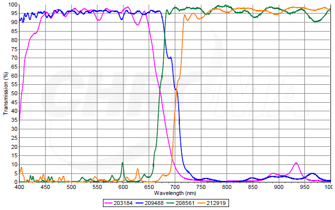
Figure 1. Transmission diagrams of the dichroic mirrors for the first CARS configuration, which utilizes a pair of Ti:sapphire lasers. For wavelengths from visible to NIR, a reflection diagram can be calculated by inversing a transmission diagram assuming zero absorption. Image Credit: Chroma Technology Corp.
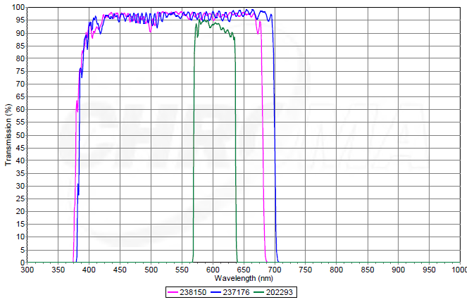
Figure 2. Transmission diagrams of the emission filters for the first CARS configuration. Image Credit: Chroma Technology Corp.
For CARS imaging, the researchers recommend using a series of two emission filters before the detector to optimize excitation laser blocking (theoretically to OD10) (Figure 3). The use of a shortpass filter (ET680sp-2P8 or ET700sp-2P8) and a bandpass filter (e.g., ET605/70m-2p) is suggested for this application.
ET680sp-2P8 and ET700sp-2P8 are specially developed filters with an average OD8 blocking of 1060 nm.
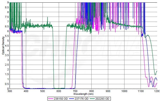
Figure 3. OD diagrams of the emission filters for the first CARS configuration. Image Credit: Chroma Technology Corp.
Two-photon filters are preferred over one-photon filters as potential bandpass filters when combined with ET680sp-2P8 or ET700sp-2P8. This is due to their increased blocking (on average, OD6) in the NIR region.
For example, ET660/30m (lot 215558) and ET740/60m (lot 242560) may both meet the spectrum requirements of specific CARS emissions. However, both exhibit spectral leakage at 900–1000 nm (Figure 4).
This leakage may allow a tiny number of excitation lasers to access the detector, resulting in a reduced S/N ratio. On the other hand, ET660/40m-2p (lot 211696) and ET750/50m-2p (lot 215534) are superior candidates for covering similar bandwidths by maintaining an average OD6 blocking over NIR (Figure 5).
Under certain conditions, certain of the one-photon filters (e.g., ET731/30m, lot 19731) that block beyond 800 nm could be used, particularly when combined with the OD8 blocking shortpass filters.
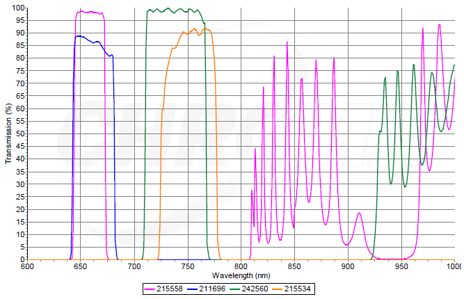
Figure 4. Transmission diagrams of representative one-photon and two-photon bandpass emission filters. Image Credit: Chroma Technology Corp.
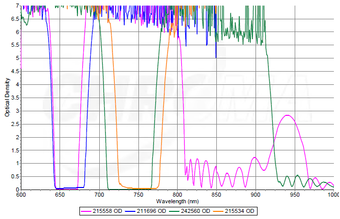
Figure 5. OD diagrams of representative one-photon and two-photon bandpass emission filters. Image Credit: Chroma Technology Corp.
This information has been sourced, reviewed, and adapted from materials provided by Chroma Technology Corp.
For more information on this source, please visit Chroma Technology Corp.