When looking to reduce development times, control costs, and attain peak performance, it is crucial to strike the right balance between individual component performance and overall system design. System designers aiming to boost the performance of both individual components and entire subassemblies will achieve the best results by adopting an optimized multi-component approach.
This article discusses key strategies for optimizing filter subassemblies through both system-level and component-specific considerations, and suggests practical tools for addressing design challenges.
System-Level Design Considerations for Subassemblies
When designing optical filter subassemblies to optimize performance while reducing costs, every element of a system requires special consideration. System designers seeking unified, optimized subassemblies should carefully select a set of components that can optimize overall system performance; this will ensure each element acts in unison for peak efficiency.
Achieving a balanced system that accounts for factors such as filter placement, beam shape, environmental conditions, and light source and detector integration is crucial for efficient, high-performance optical systems.
A diligent approach to system-level design - one that holistically evaluates each individual element - can streamline assembly, lower costs, and simplify development. Some of the fundamental areas to consider for system-level optimization are detailed below.
Imaging Versus Non-Imaging Systems
Filter specification is an essential component in designing optical imaging systems, as they have distinct requirements from non-imaging systems. Imaging specifically preserves spatial information, so filters must minimize transmitted wavefront distortion to ensure good image quality.
Components, including dichroic mirrors and other reflective optics, should produce as little reflected wavefront distortion as possible to prevent degradation of the final image.
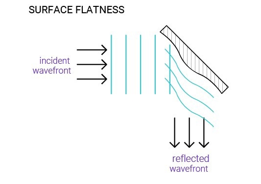
Image Credit: Chroma Technology
Moreover, in imaging systems that require precise image registration, especially where filters or dichroics are routinely exchanged, there is an emphasis on low wedge angles and tight thickness control.
Conversely, detectors such as photomultiplier tubes (PMTs) or photodiodes in non-imaging systems act as “light buckets” with no spatial information. Requirements for wavefront distortion and registration are more relaxed in non-imaging systems. However, there may still be specific factors to account for in non-imaging systems, such as those based on the spectral and intensity characteristics of the light.
For filters placed near an imaging plane, surface quality, defects, and pinholes are important factors, as they can produce visible artifacts in the image. Understanding whether a system is imaging or non-imaging early in the design process will help ensure that filters meet the application’s specific requirements without needless costs or over-specification.
Light Source and Detector Matching
When combining filters with light sources and detectors, knowledge of both the detector's sensitivity and the light source's spectral output is crucial. Distinct combinations, such as a xenon (Xe) arc lamp with a photomultiplier tube (PMT) compared to a laser with a CMOS sensor, present unique filtering requirements.
Xenon lamps typically have a broad-spectrum source, meaning filters are commonly employed to select or block certain regions of the spectrum, ensuring that only wavelengths of interest reach the detector. This is vital when using sensitive detectors such as PMTs, which can detect a broad range of wavelengths but can be vulnerable to noise from unwanted wavelengths.
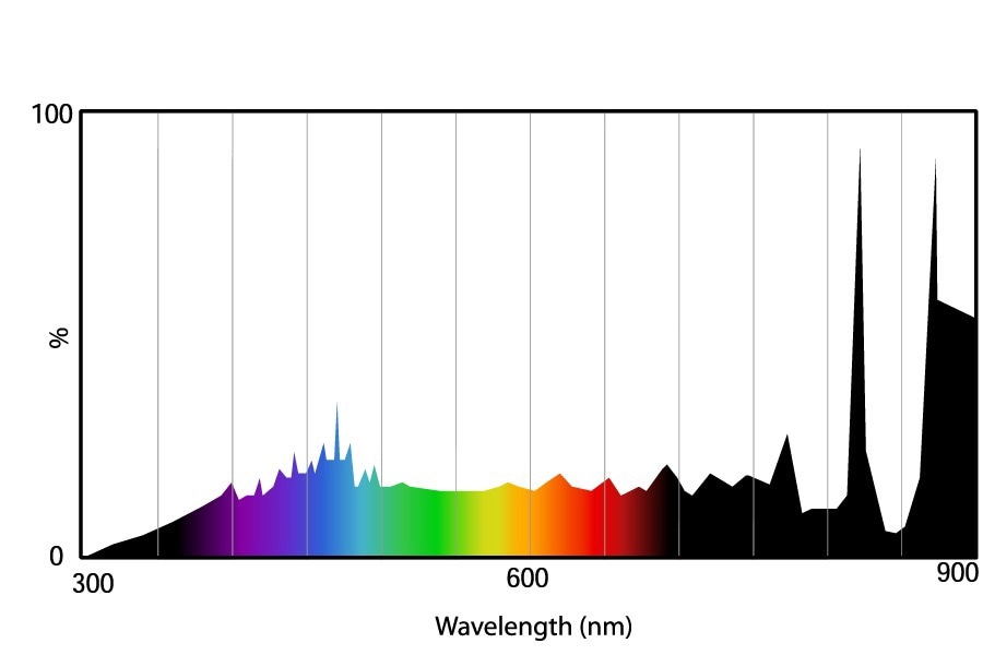
Image Credit: Chroma Technology
In contrast, lasers, which are narrow-spectrum light sources, emit light at very specific wavelengths but can sometimes produce undesirable emissions near the primary laser line. In such cases, a filter might need extremely steep transitions and a high-blocking “near-band”, but would not necessarily need blocking far from the band. Narrow-bandpass filters can be employed to further isolate the laser wavelength and prevent interference from ambient light or other spectral noise.
Regardless of the combination, having a good comprehension of the overlap between the light source’s emission spectrum and the detector’s sensitivity profile is key. This makes it easier to select the appropriate filters - such as bandpass, longpass, or shortpass filters - to boost the required signal, minimize noise, and enhance overall detection accuracy.
Filter Placement and Optical Path Considerations
Making sure filters are strategically positioned within the optical path is imperative for optimizing the balance between performance and cost. Each possible filter location in the optical path potentially offers specific benefits and limitations, determined by factors such as beam shape, cone angle, and intensity distribution.
Determining the optimal position typically enables designers to maximize efficiency while minimizing the filter's size and cost, though the best location can vary depending on the system’s specific design requirements.
The most important factor to consider regarding filter placement in the optical path is determining which filters to use early on in the design process. This will prevent expensive redesigns and ensure filters are placed seamlessly within the wider system architecture.
System designers who consider optical filters an essential component of the overall system are more likely to develop a practical, cost-effective solution that prevents misuse of filters beyond their limits, which could otherwise lead to spiraling costs and compromise functionality.
Environmental and Operational Conditions
Addressing environmental factors, including temperature, humidity, vacuum conditions, and potential radiation exposure, is crucial for durability and long-term filter stability. Systems exposed to high-intensity light conditions, whether from lasers or intense arc lamps, may need filters with specific coatings and robust thermal management.
Considering environmental conditions early in the design process prevents premature filter degradation and improves the likelihood of consistent performance across a range of operational settings.
System designers can also maximize optical filter subassemblies for both performance and cost by working closely with manufacturers when taking system-level factors into account. Establishing these core elements at the beginning clarifies the subsequent task of fine-tuning individual components, leading to an efficient, well-balanced, and cost-effective optical filter subassembly.
Optimizing Optical Filter Components for Performance and Cost
Optical filters are vital components that directly affect the performance of complex optical systems. However, there can be trade-offs in achieving optimal performance, typically involving cost and product lead time.
Distinguishing between catalog filters and bespoke solutions is a critical phase when trying to balance all considerations. Both options have distinct benefits: catalog filters are readily available off the shelf, while custom filters can be customized to meet specific system requirements.
Understanding when it is best to leverage each of the two available options provides unique advantages for system designers in relation to both cost and performance.
Catalog Versus Custom Filters: Choosing the Right Option
Catalog Filters
Pre-designed and readily available, catalog filters are well-suited for prototyping, quick replacements, or routine applications. However, they are pre-designed for general purposes and typically include features such as deep blocking and high surface quality that could be more or less than what is needed for a specific application, thus making them more costly.
Custom Filters
Designed to meet the specific performance requirements of an application, custom solutions are most effective for designing subassemblies in which several components must work in unison.
Moreover, custom filters do not include unnecessary elements that catalog filters sometimes include, ensuring efficient manufacturing and lower costs. Customization offers flexibility in performance characteristics, as angle of incidence, blocking levels, and substrate material can be configured to ensure that only what is necessary is included in the design.
Collaborating with manufacturers during the early stages of the design phase allows clients to determine whether a custom filter would be the best choice for performance and cost-efficiency compared to catalog options.
Users experience the most benefit when they consider filter characteristics that directly impact cost, lead time, and optical performance. Even the smallest adjustment to these parameters can mean custom options offer considerable savings, while with catalog filters, selecting the right off-the-shelf specifications avoids unnecessary expense.
Key Optimization Characteristics for Optical Filters
After a user has decided which filter they would benefit most from, modifying specific filter characteristics can enhance performance by aligning with system requirements while keeping costs under control.
In many cases, easing back on certain specifications, such as AOI range, blocking levels, or surface quality, yields adequate performance without the added expense of over-engineering. To achieve better performance and reduce filter component costs, the table below exhibits the most appropriate filter parameters for certain subassemblies.
Source: Chroma Technology Corp.
| Filter Parameter |
Challenge |
Solution |
| Angle of Incidence (AOI) and Cone-angle |
Filters that accept a wide range of AOIs or must be used with an incident beam with a large cone angle require advanced coatings, increasing complexity and cost. |
Narrow the AOI range or collimate the beam (use a filter in infinity space) to simplify design and reduce costs. |
| Blocking Requirements |
Deep out-of-band blocking in catalog filters is often unnecessary for certain applications. |
Customize blocking levels based on the light source and detector to reduce the number of coating layers, thereby minimizing production time and costs. |
| Edge Steepness |
Steep edges require thicker coatings, increasing cost. |
Relax the steepness when sharp transitions are not critical to save on manufacturing costs. |
| Wavelength Tolerance |
Tight wavelength tolerances mean lower yields and, therefore, higher costs. |
Loosen wavelength tolerances when possible to improve yield and reduce cost. |
| Filter Shape |
Custom filter shapes increase processing time. |
Opt for rectangular shapes to improve throughput and reduce costs. |
| Packaging |
Individual packaging increases inspection time. |
Choose bulk packaging to reduce inspection time. |
| Substrate Material |
High-end substrates, such as fused silica, are costly and not always required. |
Use cost-effective substrates or relaxed specifications, especially for non-imaging systems. |
| Surface Quality |
Strict scratch/dig requirements decrease yield. |
Relax surface quality requirements for non-imaging systems to reduce costs. |
Collaboration as the Foundation for Effective Optical Solutions
Successful development of custom optical subassemblies is dependent on close collaboration between system designers and manufacturers. Providing detailed system information, such as performance goals, environmental conditions, and system constraints, makes customization straightforward.
Most manufacturers are willing to sign NDAs to protect proprietary information, ensuring that sensitive data is shared securely. Making contact early on can help coordinate the design with the system requirements from the outset, minimizing costly redesigns.
What’s more, experienced engineers can reveal opportunities that might otherwise go unnoticed, ensuring that even the most challenging designs are feasible within reasonable timelines and costs.
Rapid Prototyping: Custom on a Catalog Timeline
When it comes to developing optical filter subassemblies, prototyping is crucial because it enables precision-engineered custom solutions on a timeline comparable to catalog filters. Early prototypes help verify designs and align them with system requirements, ensuring that the most important elements perform as expected.
The early identification of potential issues through rapid prototyping limits the chances of redesigns and delays, making even the most complex project manageable. Manufacturers like Chroma and 89 North bring together years of engineering expertise with sophisticated prototyping capabilities to refine design possibilities and streamline integration. By delivering custom solutions promptly, they help customers meet performance goals without compromising on speed or quality.
About Chroma Technology
Chroma Technology is renowned for being a leading manufacturer of extremely durable and precise optical filters. For more than three decades, Chroma has supplied precision optical filters to a wide range of industries, including the life sciences, astronomy, industrial inspection, security, and aerospace. Chroma Technology’s reputation stands on its dedicated customer service, including free technical and application support.

This information has been sourced, reviewed, and adapted from materials provided by Chroma Technology Corp.
For more information on this source, please visit Chroma Technology Corp.