Sponsored by MKS OphirReviewed by Olivia FrostJul 30 2026
High-power laser applications have grown dramatically in recent years as a result of improved production processes that allow for lower manufacturing and operating costs. High-power laser applications that were unusual a few years ago are now regarded as standard in material processing and micromachining.
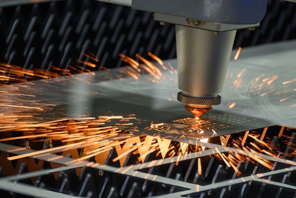
Image Credit: Pixel B/Shutterstock.com
Lasers are currently used in material processing applications such as welding, cutting, additive manufacturing, marking, and engraving, allowing for greater precision, quicker rates, and enhanced variety. In addition to the material processing business, high-power lasers are increasingly being used in military and scientific applications.
Traditionally, high-power lasers were CO2-pumped. Recent advancements and industry demands for more precise processing have transformed NIR fiber lasers into a fast expanding participant in all high-power applications, including processing, research, and defense.
Lasers are considered "high power" if their output ranges from hundreds of watts to tens of kilowatts. The vast majority of material processing lasers are 1070 nm fiber lasers, with only a few green 535 nm fiber lasers.
CO2 lasers are still widely used in material processing. However, they are being phased out in favor of fiber lasers. Ultrafast lasers (with picosecond or femtosecond pulse widths) are also being used for finer material processing.
The most popular high-power CW fiber lasers provide output powers ranging from 1 kW single-mode to more than 100 kW multi-mode. Fiber lasers are best suited for the material processing sector due to their dependability, versatility, and large range of interchangeable fiber terminations, collimation lenses, and processing heads (with both Gaussian and Top Hat beam forms).
Importantly, the range of applications and production rates requires periodic or continuous parameter monitoring to guarantee process control and quality assurance. The parameters to be monitored are:
- Spot size
- Beam shape/mode
- Focusing position
- M2
- Laser power/energy
While laser power/energy can be measured using a standard thermopile sensor with water cooling, other parameters such as spot size, beam shape, focal position, and M2 necessitate more advanced techniques to measure high-power laser parameters without distorting them or damaging the analytical equipment.
In general, three methods are employed to achieve this:
- Indirect measurement, with no contact with the beam: This approach is based on imaging the beam's Rayleigh dispersed light from the side, which is employed in the Ophir BeamWatch
- A scanning tip with a pinhole samples a tiny bit of the beam and sends it to a single-element detector. The rotational and translational scanning of the pinhole through the beam produces a two-dimensional picture of the beam profile. This approach necessitates large-scale equipment with moving mechanical components and a water chiller
- Measured directly with a CCD beam profiler, even after significant optical attenuation. The new Ophir LBS-300HP-NIR beam splitter for high-power lasers can measure NIR (1000–1100 nm) focused or collimated laser beam profiles of up to 5 kW or 15 MW/cm2
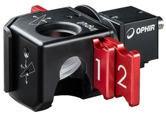
Figure 1. LBS-300HP-NIR is connected to the Ophir SP920 beam profiler camera. Image Credit: MKS Ophir
Reducing Extremely High Power
Using the LBS-300HP-NIR, a portion of the incoming beam is reflected via the front surfaces of two orthogonally aligned wedges. Less than 0.0001% (1/106) of the beam is reflected at the Ophir beam profiler camera, and less than 0.1% towards the optional Ophir power meter.
The remaining 99.9% of the incoming laser beam is transferred. This allows measurement of beam form, focus spot, beam waist, M2, and total power of lasers up to 5 kW or 15 MW/cm2.
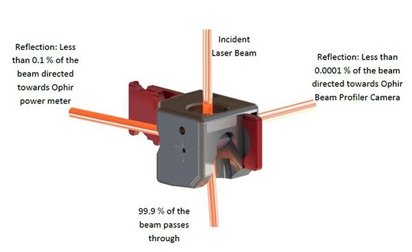
Figure 2. Illustration of beam splitting directions. Image Credit: MKS Ophir
The LBS-300HP-NIR delivers uniform attenuation of any beam shape, including Gaussian, flat-top, and doughnut modes, while retaining the input laser beam's polarization and profile. This generates an accurate, high-fidelity sample of the incident beam.
The LBS-300HP-NIR enclosure features various mounting points for simple and diverse installation options.
The C-mount stackable design works with other C-mount accessories. A set of six replaceable ND filters is provided to modify the beam's intensity before it reaches the camera imager. Thus, the LBS-300HP-NIR can profile high-power laser beams using CCD beam profilers.
Because of the extremely high beam attenuation during high-power laser emission, scattered NIR light may interfere with beam measurement by increasing background illumination. To minimize scattering, it is advised that the beam profiler camera be separated by 50–100 mm using the C-mount extension tube.
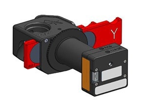
Figure 3. LBS-300HP-NIR is attached to SP928 CCD beam profiler via C-Mount tube for longer focal depth and reduced scattering. Image Credit: MKS Ophir
Flexible Setup Options
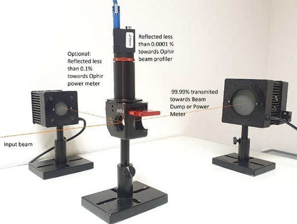
Figure 4. Example I of the LBS-300H-NIR setup for high-power laser measurement. Image Credit: MKS Ophir
- The incident beam was reflected with less than 0.0001% towards the Ophir SP920 beam profiler using an ND-filter slide and C-mount extension tube, reducing scattering on the CCD and eliminating ambient light
- 0.1% of the original intensity can be pointed to the optional Ophir L30C power/energy sensor
- 99.99% of incident lasers are refracted 6 ° towards the beam dump
- The incident beam was reflected at less than 0.0001% toward the Ophir SP920 beam profiler using a C-mount extension tube to limit scattering on the CCD and remove ambient light
- Only 0.1% of the original intensity is directed towards the optional Ophir PD300R photodiode sensor, with the remaining 99.9% passing through
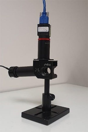
Figure 5. Example II of LBS-300HP-NIR setup for high power laser measurement. Image Credit: MKS Ophir
Several validation measures were conducted to determine the LBS-300HP-NIR specs and capabilities:
Beam Profile Accuracy
To test the accuracy of the beam profile sample, a comparison was made between the LBS-300HP-NIR and a normal Ophir LBS-300s-NIR attenuator using Ophir BeamGage software and a camera.
The LBS-300s attenuates the laser beam by 1000, but the LBS-300HP-NIR attenuates it by more than 1,000,000; to balance the attenuations and obtain comparable laser power, extra optical components were used with LBS-300s.
A 100 W Gaussian fiber laser was employed to evaluate the attenuators. The resultant beam profile comparison shows comparable profiles and diameters. The profile obtained after LBS-300HP-NIR attenuation is clearer since there are fewer optical surfaces in the beam path.
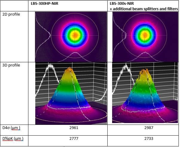
Figure 6. BeamGage software - Beam profile comparison between LBS-300HP-NIR and classic LBS-300s attenuation of 100 W fiber laser. Image Credit: MKS Ophir
High Power-Density Measurements
Power-density tests were carried out with a concentrated beam from a single-mode 1 kW fiber laser. The 1 kW beam was focused to 340 μm and 91 μm, yielding beam samples with power densities of 2 MW/cm2 and up to 30 MW/cm2 on the camera CCD.
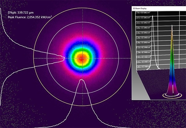
Figure 7A. Demonstration of 340 μm beam; 2 MW/cm2 power density beam profiling using BeamGage at high power density. Image Credit: MKS Ophir
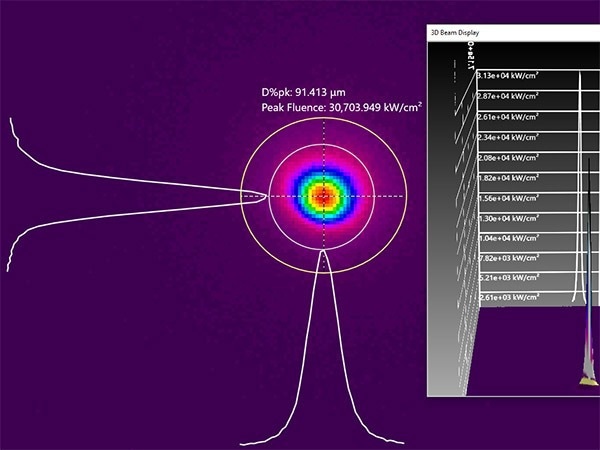
Figure 7B. Demonstration of 91 μm beam width; 2 MW/cm2 power density beam profiling using BeamGage at high power density. Image Credit: MKS Ophir
High Power Measurement
To assess the attenuation properties of the LBS-300HP-NIR with a high-power laser, a beam profile of a multi-mode 5 KW collimated laser was measured. The generated profiles demonstrate comparable beam characteristics across different laser strengths.
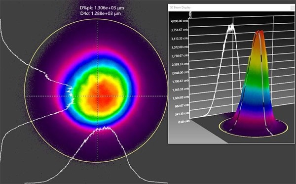
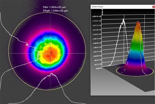
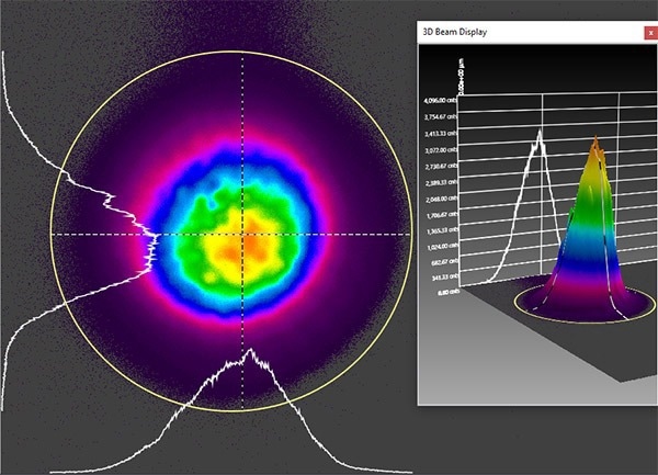
Figure 8. BeamGage image of beam profile of A: 5 KW, B: 3.5 KW, C: 2 KW laser power. Image Credit: MKS Ophir
Thermal Tests
High-intensity laser irradiation through UVFS wedges may cause the LBS-300HP-NIR assembly temperature to rise. Graph 1 shows the temperature rise after 10 minutes of irradiation. For example, at 4 kW power, the temperature increases by 23.4 °C.
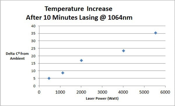
Chart 1. Increase from ambient temperature after 10 minutes of laser irradiation. Image Credit: MKS Ophir
Shorter measurement times are recommended to prevent overheating of the LBS-300HP-NIR when using high-power lasers. Graph 2 shows the heating behavior over time. For example, after 15 minutes of 2 kW lasing, the temperature rises by 20.4 °C.
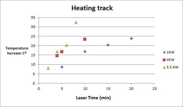
Chart 2. Increase from ambient temperature vs. lasing period for 2, 4 and 5.5 KW. Image Credit: MKS Ophir
During lengthy periods of high-power lasing, both active and passive cooling of the LBS-300HP-NIR system are advised.
Conclusions
The LBS-300HP-NIR provides practical and economical high-power laser beam profile measurements by offering optical attenuation by a factor of more than one million, allowing for precise measurements of beam profile, beam diameter, M2, and focal point position.
The LBS-300HP-NIR, when paired with a beam profiler, can be used alone or as part of a system or laser work cell.
Acknowledgments
Produced using materials originally authored by Yoni Groisman, Application Engineer at MKS.

This information has been sourced, reviewed and adapted from materials provided by MKS Ophir.
For more information on this source, please visit MKS Ophir.