Sponsored by MKS OphirReviewed by Olivia FrostJul 29 2026
High-powered industrial lasers are useful instruments for material processing. Maintaining optimal performance and improving the procedures used can increase throughput and reduce downtime.
Image Credit: Pixel B/Shutterstock.com
Periodic measurements and long-term monitoring of important laser variables, such as laser output power, focused spot size, and focus-spot temporal position, give the information required to improve accuracy and optimize your process.
The fiber laser, which has high wall-plug efficiency and beam quality, has altered how parts are produced using lasers. What has not changed is the necessity for high power densities to achieve varied outputs in material processes, as well as process control.
Focus Shift
As the need for greater laser powers grows, the problem of stresses on laser system components becomes more common. One of them, "focus shift," is induced by thermal effects on the laser's components, particularly transmissive optics such as focusing lenses and protective cover slides.
When the focus is adjusted while keeping the distance between the laser's processing head and the material constant, the power density varies, changing how the laser interacts with the material. Many industrial laser applications rely on precisely determining where the focused spot is in relation to the parts being treated.
Power or energy density refers to how much power (continuous wave or average power lasers) or energy (pulsed lasers) is concentrated in a given quantity of area. A 4000 W laser, for example, concentrated to a 100-micron-diameter spot size, produces a power density of about 51 MW per cm2.
The power density of the laser influences the outcome of the contact with the material. Due to the way the laser interacts with these two materials, plastic ablation requires far less power density than cutting one-inch steel.
To guarantee that a process remains constant across time, it must be measured and controlled. Most laser users engaged in material processing believe that monitoring the laser's power and spot size is critical.
The fiber laser's reputation for producing high-quality beams has led some laser users to believe that process control is less critical once the laser is in production.
The simple fact is that regardless of the lasing medium, the laser is still composed of matter, which degrades over time. This characteristic, along with the typically unclean manufacturing conditions in which industrial lasers are used, results in a laser system that evolves with time.
These modifications result in reduced laser power delivered to the workpiece and altered thermal effects of the laser light on its components. Only by following a strict process control routine can the laser user accurately forecast when to undertake maintenance on their laser system to keep its process optimized for top performance.
Laser Power Measurement
Historically, laser power measurement suppliers have provided laser users and technicians with power meter systems that are easily installed in work cells, integrate directly into logical environments, protect against laser-processing debris when not in use, and are simple to maintain and calibrate.
These meters take periodic measurements to assess laser performance consistency over time, which is useful for maintaining laser quality, optimizing maintenance schedules, and troubleshooting.
Many manufacturing conditions, as well as the debris generated during their operations, are hard on laser systems, reducing their efficiency quickly and considerably. Process debris collecting on the processing head's protective cover slide can restrict laser power to such an extent that the quality of the components produced suffers substantially.
Laser power measurement is the first step in ensuring that the laser performs consistently throughout time. However, due to the phenomenon of focus shift, a laser's power measurement only tells part of the picture.
As a result, laser measurement suppliers employ two ways to calculate the size of the concentrated spot and its location in relation to the processing head, allowing the necessary laser power density to be maintained at the workpiece.
At-Focus Beam Measurement
Scanning slit profiling devices, such as Photon's NanoScan products, provide an accurate method for immediately estimating the size of a focused spot. A rotating drum spins two orthogonal slits around a single-element detector, gradually exposing the laser.
The drum's location communicates with an encoder, allowing it to properly reconstruct the laser’s size and mathematically represent both 2D and 3D laser profiles at the same time.
The relative power density of the laser being profiled without attenuation is high because the laser is gradually exposed. This is a key advantage of this approach.
Scanning slit profilers can be placed directly in the beam path to scan the laser's focused spot, which can typically handle up to 1000 W of laser power (depending on its size).
This approach allows the laser user to set his concentrated spot at the site of measurement without sampling or absorbing the beam, ensuring that it is the proper size and does not change over time. The laser user may also quickly and simply calculate the optimal distance between the laser system and the part being treated.
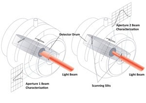
Figure 1. Diagram of the operation of a scanning slit profiler. Image Credit: MKS Ophir
This beam-measuring technique is highly beneficial in the processing of medical equipment. Measurement of the focused spot (in addition to process laser power) is critical, and sometimes required during the application development, system run-off, and ongoing process validation stages.
Access to the laser's beam path after integration into a system and production is frequently limited owing to mechanical interferences, so it can be difficult to sample the beam for attenuation.
Scanning slit profilers have a compact footprint and need minimal attenuation. Therefore, they have been successfully employed to measure the concentrated spot on continuous wave or quasi-CW beams.
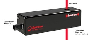
Figure 2. Spiricon’s BeamWatch product in relation to the laser being analyzed. Image Credit: MKS Ophir
Non-Contact Beam Measurement
Ophir-Spiricon has announced BeamWatch®, a camera-based, non-contact beam-profiling technology. It delivers data to users of multi-kilowatt, one micron-wavelength lasers that have never been observed with any other beam profiling technology.
The signal delivered to and evaluated by the product is based on Rayleigh scattering, a physical phenomenon in which tightly focused light near the laser's beam waist is scattered off nearby air molecules and captured by the camera. This enables an investigation of the laser's waist without coming into contact with the beam.
The end product is a beam analyzer that does not require water cooling, has no moving parts, and has no top power restriction for the laser being studied. Furthermore, because it is a camera-based system, it delivers data up to 15 times per second, allowing the user to view additional time-dependent aspects of their laser system.
The device incorporates laser technician-specific software that measures the size of the laser spot (or "beam waist") and its position over time.
To better define their laser system, the user may monitor and graph the amount and rate at which the spot shifts. In non-contact beam measurement, the camera and telecentric lens examine the laser's Rayleigh length, which includes the beam path above and below the focused area.
As a consequence, measurements of beam divergence (M2) and beam parameter product (BPP) may be delivered in real time. The system also has an optional, simpler "user interface" that shows green and red go/no-go readings on key laser parameters based on specified user criteria to allow for rapid periodic assessments of the whole laser system.
Many industrial laser applications that employ multi-kilowatt lasers rely on measuring the concentrated spot size and placement to assure accurate and constant laser power densities. It was not until the introduction of BeamWatch™ that laser users had a mechanism to measure these characteristics.
For example, in some automobile welding applications, processing occurs some distance from focus because a broader beam with a lower power density delivers the necessary outcomes.
If the focused spot shifts due to thermal effects in the laser system after the beam is turned on, the position of the concentrated spot is not constant. Therefore, the beam's power density varies, resulting in an inconsistent outcome over the course of the weld.
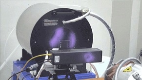
Figure 3. Spiricon’s BeamWatch® in the forefront and Ophir’s 100 kW Power Measurement System in the background measuring a 100 kW fiber laser. Image Credit: MKS Ophir
Laser drilling for aeronautical and aerospace part manufacture is another laser application in which the focal point placement is crucial. During these operations, thousands of small holes are drilled into parts to air-cool them, which would otherwise be damaged or distorted during usage.
These holes are drilled using high-power lasers with rather long focal-length lenses. The concentrated point, where the laser's power density is highest, must be identified and carefully placed on the part being processed so that each hole.
Reflective Optics at High Powers
Recent developments in beam delivery systems have resulted in innovative approaches to the problem of focus shift. Laser application professionals employed Spiricon's noncontact beam analyzer to assist in building these cutting-edge technologies.
One design feature that helps with this problem is the use of reflected optics rather than transmissive optics, which are more subject to heat effects from the laser.
As laser power increases, it is used in industrial operations. Recently, measurements were taken with Spiricon's BeamWatch system on a 100-kilowatt fiber laser focused with reflecting optics.
Because of the relatively high laser intensity, this processing head showed an estimated 8 mm change in focus from beam-on to around 20 seconds later. The reality is that lasers will continue to have thermal impacts on the system components into which they are incorporated.
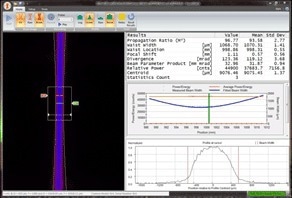
Figure 4. BeamWatch’s Technician’s Interface showing the shift of the focused spot from the red marker where the spot started to the green marker where the spot currently is. Image Credit: MKS Ophir
Production facilities are under increasing pressure to improve their operations, enhance throughput, limit downtime and operational costs, and reduce scrap. Fortunately, laser users and technicians have a variety of instruments at their disposal to enhance laser efficiency and maintain constant high-quality laser operations.
The latest technologies in laser systems can help achieve these objectives and better characterize and optimize their performance.
Author Bio
John McCauley joined Ophir-Spiricon in January 2009 and currently works as a Product Specialist for the company's laser measuring equipment. Prior to that, he worked as an end user and applications engineer on laser marking and engraving systems.
He has been involved in and contributed to the instruction of various Laser Safety Officer, Laser Measurement, and Laser Application Technology courses. John also served in the US Navy as a nuclear-qualified machinist mate aboard fast-attack submarines based in Pearl Harbor, Hawaii.
Acknowledgments
Produced using materials originally authored by John McCauley, Product Specialist at Ophir-Spiricon.

This information has been sourced, reviewed and adapted from materials provided by MKS Ophir.
For more information on this source, please visit MKS Ophir.