Topological insulators (TIs) are novel materials that can enable electron transport on the top but is an insulator on the inside. Surface states in TIs are resistant to disturbance and flaws in the bulks, unlike surface states in regular insulators. These intriguing properties address impurity difficulties in bulk topology materials and pique interest in the field of topological photonics.

Image Credit: AerialVision_it/Shutterstock.com
As a result, there has been a lot of interest in studying topological-phase transitions and edge states in optical devices that are susceptible to local perturbations and manufacturing errors, such as lasers. It is feasible to create lasing at the topological edge states by adding active components in photonic topological structures.
In comparison to conventional bulk-state lasers, the resultant topological edge-state lasers have a low lasing threshold and are resistant to manufacturing and local flaws. In numerous situations, topological edge-state lasers have recently been shown. Based on the PT-symmetry in non-Hermitian systems, several new unique phenomena and optical devices have been suggested and realized.
Non-hermiticity in photonic topological systems has been investigated and proved experimentally. It was also shown that complementing topological protection with non-Hermitian symmetries can improve the topological midgap state by generating a defect site in the middle of gain/loss sites. Because of the intrinsic non-Hermiticity in laser systems, topological lasers provide an appropriate platform in this context.
In this paper, researchers show how a one-dimensional Su–Schrieffer–Heeger (SSH) Fabry–Perot (FP) laser chain with gain and loss waveguides and an active gain topological defect may lase in a topological edge state. The active topological defect is used to magnify the density of state (DOS) of the midgap states that are spontaneously produced in the system by violating the PT symmetry.
When compared to other bulk modes, these states preserve their topological features while having the lowest lasing threshold. The dynamic evolution of the dispersion relationship is explored by tweaking bias levels in gain/loss sites, and the phase transition from the trivial to topological state is manifested using incremental bias levels.
Finally, to preserve the suggested system’s symmetry, a reconfiguration of the gain/loss site that is a temporal reversal of the original one is investigated. Lasing may also be achieved in the SSH chain in time-reversal configurations by electrically tweaking the gain and loss in the SSH laser chain.
Methodology
The dimer chain is depicted in Figure 1a, with C1 and C2 representing the intradimer and interdimer coupling coefficients, respectively, and C1 > C2. The heterostructures of the InAs QD lasers generated using the molecular beam epitaxy (MBE) system are shown in Figure 1b.
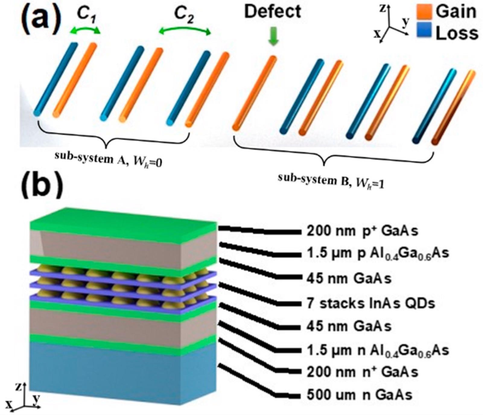
Figure 1. (a) Schematic of the proposed non-Hermitian SSH dimer chain, with staggered gain (orange) and loss (blue) waveguides, except the center single defected gain waveguide. C1 and C2 represent the coupling coefficients for intradimer and interdimer, respectively, where C1 > C2. (b) Heterostructures of the InAs QD lasers grown by molecular beam epitaxy. Image Credit: Li, et al., 2022
The DOS was computed with a passive defect in the center, and all modes were divided into two groups and separated by the central gap, as shown in Figure 2a. Topologically generated states in the midgap were amplified while states in the upper and lower groups were repressed by putting a gain into the center defect, as illustrated in Figure 2b.
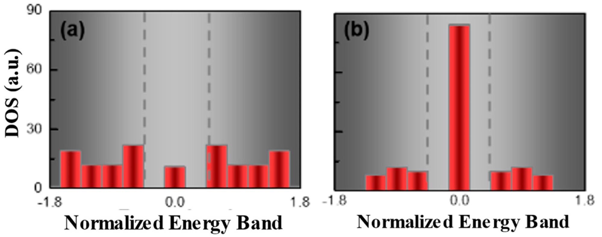
Figure 2. The density of states (DOS) of SSH chain without (a) and with (b) active defect, where the energy band was presented as normalized energy E/C1. In passive system (a), with zero gain, DOS of zero-energy states presented as less dominant compared to other bulk modes; on the contrary, in the active system (b), the DOS of the zero-energy mode was largely enhanced as a dominant mode by including an active defect. Image Credit: Li, et al., 2022
Figure 3 displays the eigenvalues and dispersion relation for various γ = g/C1, a dimensionless parameter, where g was the gain applied to the FP waveguides. The topological zero-mode showed complex eigenvalues with any nonzero gain, as seen in the red circles in Figure 3a–c. In phase I, only the zero mode, indicated by the yellow curve, had a complex eigenvalue with a gain, and the SSH laser chain lased at a single topological mode, as shown in Figure 3d.
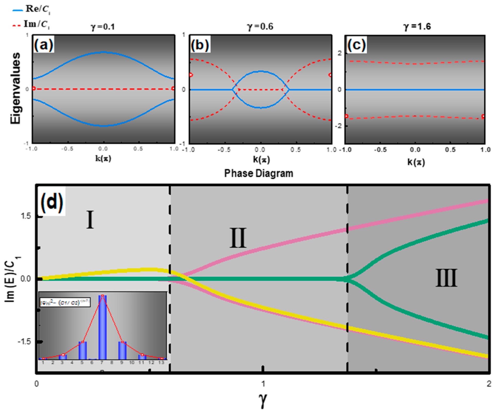
Figure 3. Complex eigenvalue diagrams of the SSH laser chain system in phase I (a), II (b), and III (c), and red circles denote imaginary parts of the topological zero state. (d) Phase diagram of the complex SSH chain, the yellow curve (color online) represents the topological mode, pink and green curves show the representative bulk modes in the system. The inset shows the topological mode profile calculated at γ = 0.1, along with the theoretical profile ∝(t1/t2)−|n| (red curve). Image Credit: Li, et al., 2022
Figure 4a represents the topological system’s band diagram with no gain or loss. Figure 4b depicts the dynamic evolution of complex eigenvalues with γ values ranging from 0.1 (blue dots) to 0.3 (red dots).
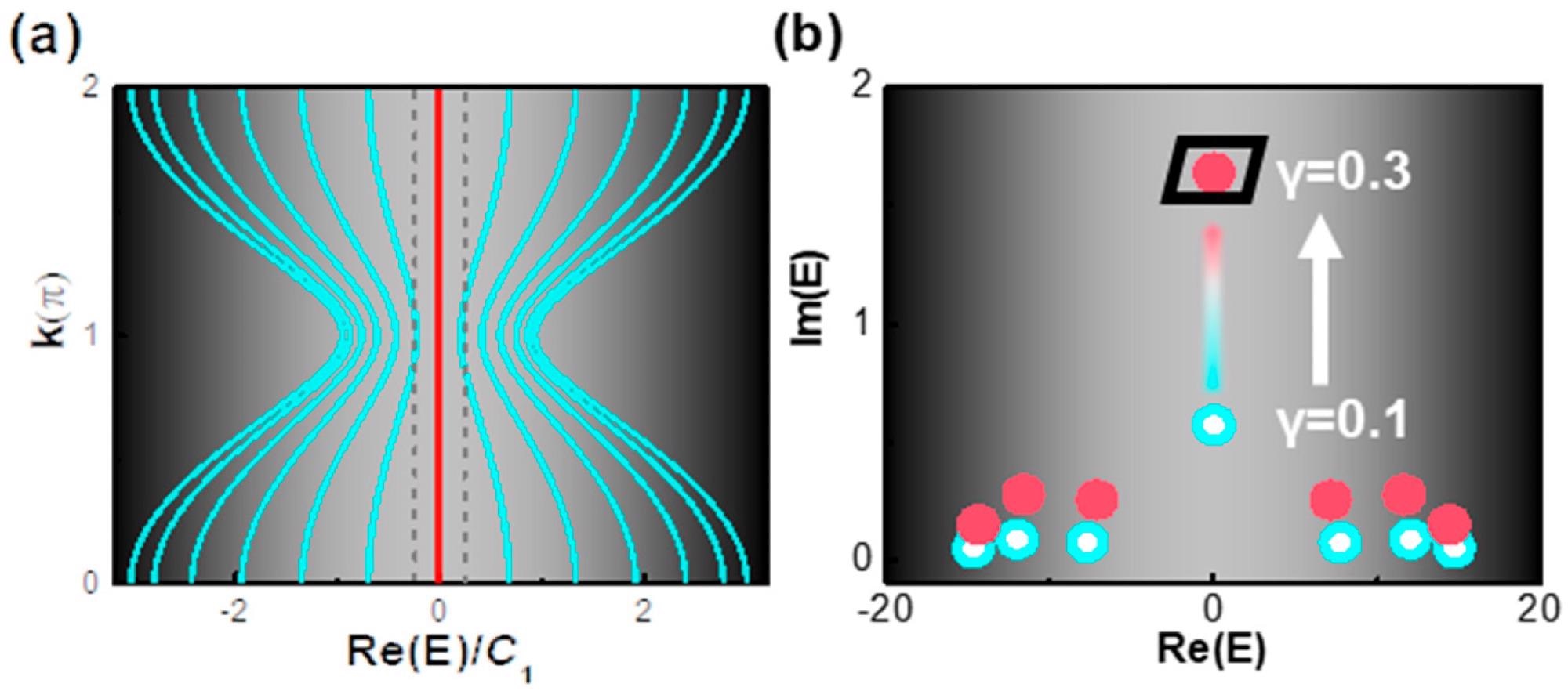
Figure 4. (a) Band diagram of SSH chain with neither gain nor loss: a bandgap presents clearly between two gray dashed lines, where the midgap states (red) sit in between. (b) Evolution of complex eigenvalues with the γ varied from 0.1 (blue dots) to 0.3 (red dots): the gain increment of the topological zero-mode was ~10 times the ones of trivial modes (with nonzero real eigenvalue) as the gain level increased. Image Credit: Li, et al., 2022
Results
The manufactured laser device is shown in Figure 5a as a top-view scanning electron microscope (SEM) picture, with the finger patterns providing individually regulated gain and loss laser waveguides. The light–current (L–I) characteristic of the SSH-coupled waveguide laser chain is shown in Figure 5b.
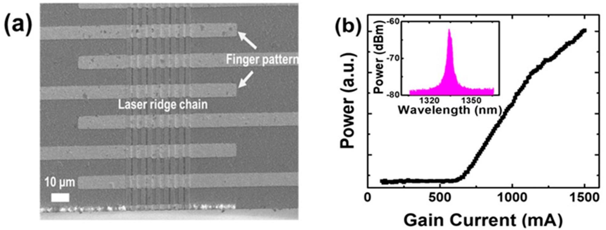
Figure 5. Top-view SEM image (a) and light–current (L–I) characteristic (b) of the SSH laser chain. It was observed that the lasing threshold current was ~600 mA. Inset: electroluminescence (EL) spectrum of the laser chain. The lasing wavelength was at 1.33 µm. Image Credit: Li, et al., 2022
The near-field patterns from the laser chain were evaluated at different gain bias currents, as shown in Figures 6a–c. The intensity line scans of the near-field pictures are shown in Figure 6d. The narrow dynamic range of the near-infrared (NIR) camera caused the intensity saturation.

Figure 6. Near-field patterns measured at varied gain bias currents: (a–c) bias current was 630 mA, 700 mA, and 730 mA. (d) The corresponding intensity line scans the different bias currents. Image Credit: Li, et al., 2022
Figure 7a depicts the topological mode and bulk mode lasing optical field distributions for a lossy defect system at | γ |=1.2. Instead of lasing at a single topological mode, simultaneously topological and bulk modes were lased simultaneously, as seen in Figure 7b, and the observed near-field pattern indicated their superposition.
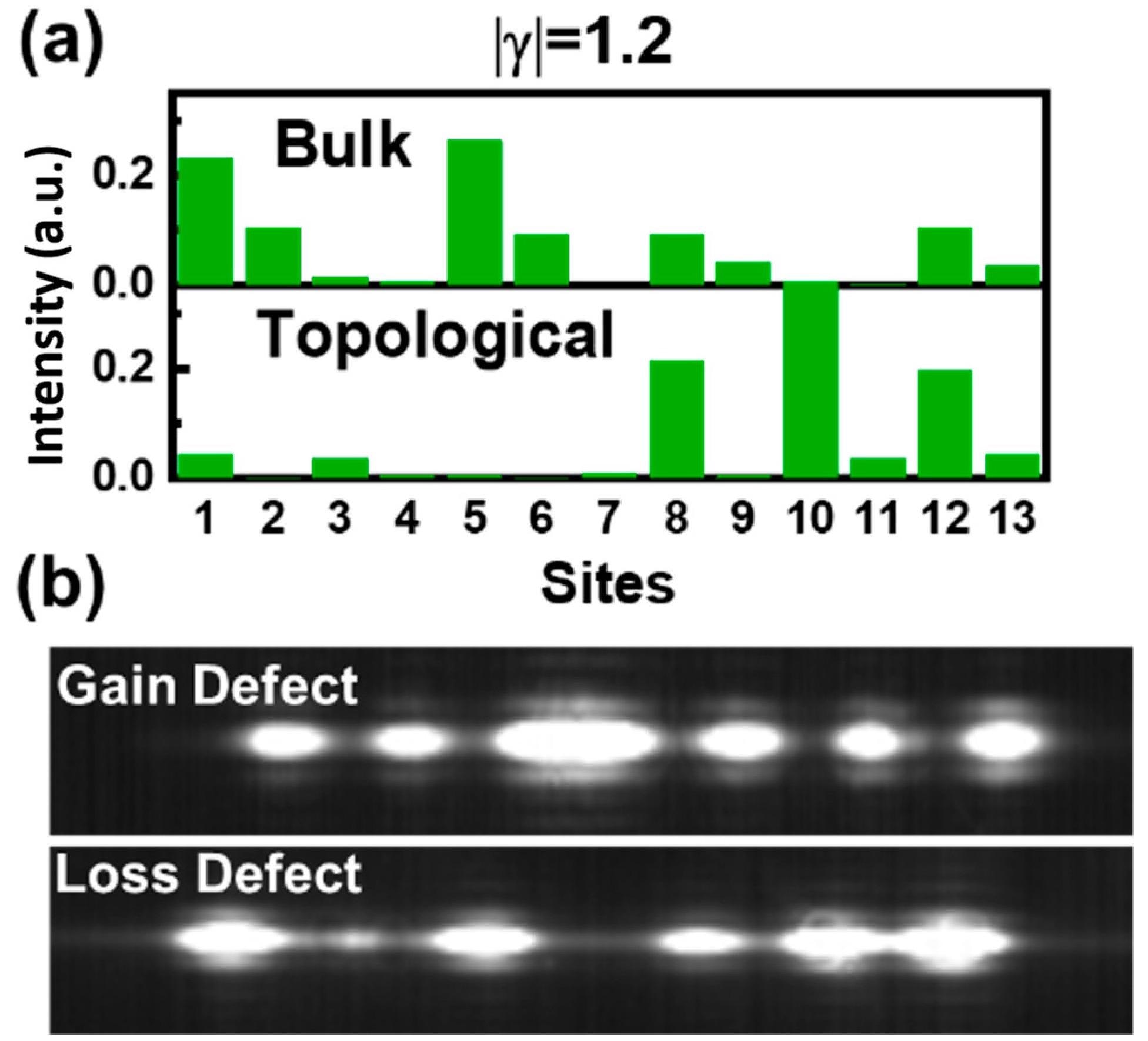
Figure 7. (a) The optical field intensity distribution of bulk mode and topological mode in configuration with lossy defect, where normalized lossy value was given as |γ| = g/C1 = 1.2; (b) near-field characteristics of the gain and lossy defected topological lasers. Image Credit: Li, et al., 2022
Discussion
A Veeco Gen-II Molecular Beam Epitaxy (MBE) system was used to build the QD laser heterostructure on a Si-doped GaAs (100) substrate. The QD laser heterostructures’ waveguide core and cladding layers were made of GaAs and Al0.4Ga0.6As, with thicknesses of 300 nm and 1.5 µm, respectively.
Seven layers of InAs quantum dot gain material with a height of ~5 nm were used in the active area. A 30 nm GaAs spacer layer was used to separate the QD layers. At ~1.3 µm, the QD laser waveguide was designed.
Standard microfabrication techniques were used to create the topological SSH laser chain. The ridge width of 3 µm was defined using an AS200 stepper aligner, and an Oxford ICP 380 plasma etcher defined the isolation trench gap widths of 1 and 2 µm during manufacturing. On ~1x1 cm2 epitaxial wafers, 24 laser arrays were constructed, with over 90% of the laser bars exhibiting lasing. Similar topological phase shifts were found across all lasing devices.
The SSH laser chain’s near-field patterns were measured. The pattern was taken using an Alpha NIR camera through a Mitutoyo FS-70 standard microscope body, and an x100 Mitutoyo NIR objectives lens focused the emission from the SSH laser chain. External illumination and microscope eyepieces were used to place the objective with laser facets.
Conclusion
Researchers developed an electrically injected topological laser in an SSH chain with an active gain defect. Phase transitions between the lasing of topological and bulk modes were detected during a theoretical investigation of the SSH chain. The suggested topological laser system’s lasing was proven experimentally with a lasing threshold of 600 mA.
A lossy defect topological laser to reconfigure the system was also studied. In terms of the topological SSH chain’s reconfigurability, the lossy topological defect configuration served as a possible innovative platform for applications such as optical modulators and detectors, where the increased absorption was advantageous. Furthermore, future research should investigate symmetric biasing on configurations.
Journal Reference:
Li, H., Yao, R., Zheng, B., An, S., Haerinia, M., Ding, J., Lee, C.S., Zhang, H. and Guo, W. (2022) Electrically Tunable and Reconfigurable Topological Edge State Laser. Optics, 3(2), pp.107-116. Available Online: https://www.mdpi.com/2673-3269/3/2/13/htm.
References and Further Reading
- Qi, X. L., et al. (2008) Topological field theory of time-reversal invariant insulators. Physical Review B, 78, p. 195424. doi.org/10.1103/PhysRevB.78.195424.
- Fu, L & Kane, C L (2007) Topological insulators with inversion symmetry. Physical Review B, 76, p. 045302. doi.org/10.1103/PhysRevB.76.045302.
- Köenig, M., et al. (2007) Quantum Spin Hall Insulator State in HgTe Quantum Wells. Science, 318, pp. 766–770. doi.org/10.1126/science.1148047.
- Hsieh, D., et al. (2008) A topological Dirac insulator in a quantum spin Hall phase. Nature, 452, pp. 970–974. doi.org/10.1038/nature06843.
- Hasan, M Z & Kane, C L (2010) Colloquium: Topological insulators. Reviews of Modern Physics, 82, pp. 3045–3067. doi.org/10.1103/RevModPhys.82.3045.
- Hsieh, D., et al. (2009) Observation of Time-Reversal-Protected Single-Dirac-Cone Topological-Insulator States in Bi2Te3 and Se2Te3. Physical Review Letter, 103, p. 146401. doi.org/10.1103/PhysRevLett.103.146401.
- Qi, X L & Zhang, S C (2009) The quantum spin Hall effect and topological insulators. Physics Today, 63, pp. 33–38. doi.org/10.1063/1.3293411.
- Qi, X L & Zhang, S C (2011) Topological insulators and superconductors. Rev. Mod. Phys., 83, 1057–1110. doi.org/10.1103/RevModPhys.83.1057.
- Fu, L & Kane, C L (2008) Superconducting Proximity Effect and Majorana Fermions at the Surface of a Topological Insulator. Physical Review Letter, 100, p. 096407. doi.org/10.1103/PhysRevLett.100.096407.
- Poli, C., et al. (2015) Selective enhancement of topologically induced interface states in a dielectric resonator chain. Nature Communications, 6, p. 6710. doi.org/10.1038/ncomms7710.
- Rechtsman, M.C., et al. (2013) Photonic Floquet topological insulators. Nature, 496, pp. 196–200. doi.org/10.1038/nature12066.
- Umucalılar, R.O & Carusotto, I (2011) Artificial gauge field for photons in coupled cavity arrays. Physical Review A, 84, p. 043804. doi.org/10.1103/PhysRevA.84.043804.
- Hafezi, M., et al. (2011) Robust optical delay lines with topological protection. Nature Physics, 7, pp. 907–912. doi.org/10.1038/nphys2063.
- Fang, K., et al. (2012) Realizing effective magnetic field for photons by controlling the phase of dynamic modulation. Nature Photonics, 6, PP. 782–787. doi.org/10.1038/nphoton.2012.236.
- Hafezi, M., et al. (2013) Imaging topological edge states in silicon photonics. Nature Photonics, 7, pp. 1001–1005. doi.org/10.1038/nphoton.2013.274.
- Cheng, X., et al. (2016) Robust reconfigurable electromagnetic pathways within a photonic topological insulator. Nature Materials, 15, pp. 542–548. doi.org/10.1038/nmat4573.
- Lu, L., et al. (2014) Topological photonics. Nature Photonics, 8, 821. doi.org/10.1038/nphoton.2014.248.
- Bandres, M. A., et al. (2018) Topological insulator laser: Experiments. Science, 359, p. eaar4005. doi.org/10.1126/science.aar4005.
- Parto, M., et al. (2017) Complex edge—State phase transitions in 1D topological laser arrays. . doi.org/10.1364/CLEO_QELS.2018.FM2E.5.
- Zhao, H., et al. (2018) Topological hybrid silicon microlasers. Nature Communications, 9, p. 981. doi.org/10.1038/s41467-018-03434-2.
- St-Jean, P., et al. (2017) Lasing in topological edge states of a one-dimensional lattice. Nature Photonics, 11, pp. 651–656. doi.org/10.1038/s41566-017-0006-2.
- Parto, M., et al. (2018) Edge-Mode Lasing in 1D Topological Active Arrays. Physical Review Letters, 120, p. 113901. doi.org/10.1103/PhysRevLett.120.113901.
- Bahari, B., et al. (2017) Nonreciprocal lasing in topological cavities of arbitrary geometries. Science, 358, pp. 636–640. doi.org/10.1126/science.aao4551.
- Pilozzi, L & Conti, C (2017) Topological cascade laser for frequency comb generation in PT-symmetric structures. Optics Letters, 42, pp. 5174–5177. doi.org/10.1364/OL.42.005174.
- Longhi, S (2018) Non-Hermitian Gauged Topological Laser Arrays. Annals of Physics, 530, p. 1800023. doi.org/10.1002/andp.201800023.
- Wu, Y., et al. (2017) Applications of Topological Photonics in Integrated Photonic Devices. Advanced Optical Materials, 5, p. 1700357. doi.org/10.1002/adom.201700357.
- Rüter, C.E., et al. (2010) Observation of parity-time symmetry in optics. Nature Physics, 6, p. 192. doi.org/10.1038/nphys1515.
- Guo, A., et al. (2009) Observation of P T-symmetry breaking in complex optical potentials. Physical Review Letters, 103, p. 093902. doi.org/10.1103/PhysRevLett.103.093902.
- El-Ganainy, R., et al. (2007) Theory of coupled optical PT-symmetric structures. Optics Letter, 32, pp. 2632–2634. doi.org/10.1364/OL.32.002632.
- Feng, L., et al. (2011) Nonreciprocal Light Propagation in a Silicon Photonic Circuit. Science, 333, pp. 729–733. doi.org/10.1126/science.1206038.
- Peng, B., et al. (2014) Parity-time-symmetric whispering-gallery microcavities. Nature Physics, 10, pp. 394–398. doi.org/10.1038/nphys2927.
- Feng, L., et al. (2014) Single-mode laser by parity-time symmetry breaking. Science, 346, pp. 972–975. doi.org/10.1126/science.1258479.
- Chong, Y., et al. (2011) P T-Symmetry Breaking and Laser-Absorber Modes in Optical Scattering Systems. Physical Review Letters, 106, p. 093902. doi.org/10.1103/PhysRevLett.106.093902.
- Hodaei, H., et al. (2014) Parity-time-symmetric microring lasers. Science, 346, pp. 975–978. doi.org/10.1126/science.1258480.
- Su, W.P., et al. (1979) Solitons in polyacetylene. Physical Review Letters, 42, p. 1698. doi.org/10.1103/PhysRevLett.42.1698.
- Malkova, N., et al. (2009) Observation of optical Shockley-like surface states in photonic superlattices. Optics Letter, 34, pp. 1633–1635. doi.org/10.1364/OL.34.001633.
- Delplace, P., et al. (2011) Zak phase and the existence of edge states in graphene. Physical Review B, 84, p. 195452. doi.org/10.1103/PhysRevB.84.195452.
- Zak, J (1989) Berry’s phase for energy bands in solids. Physical Review Letters, 62, p. 2747. doi.org/10.1103/PhysRevLett.62.2747.
- Bender, C.M., et al. (2013) PT quantum mechanics. Philosophical transactions. Series A, Mathematical, physical, and engineering sciences, 371, p. 20120523. doi.org/10.1098/rsta.2012.0523.
- Weimann, S., et al. (2016) Topologically protected bound states in photonic parity-time-symmetric crystals. Nature Materials, 16, pp. 433–438. doi.org/10.1038/nmat4811.
- Yuce, C (2015) Topological phase in a non-Hermitian PT symmetric system. Physics Letter A, 379, pp. 1213–1218. doi.org/10.1016/j.physleta.2015.02.011.
- Coldren, L.A., et al. (2012) Diode Lasers and Photonic Integrated Circuits; John Wiley & Sons: Hoboken, NJ, USA.