Modern space telescopes are no longer restricted to optical design alone. As aperture size grows and wavefront requirements tighten, the primary challenge shifts from designing an ideal optical system to maintaining it under launch loads, deployment uncertainty, cryogenic cooldown, thermal cycling, structural drift, and long-term orbital operation.
In this setting, six-degree-of-freedom positioning devices are more than just alignment tools. They form part of the telescope's error-budget management design. 6-DOF systems bridge the gap between theoretical optical performance and real in-orbit wavefront stability by managing optical component translations and rotations.
For space telescopes, the challenge is not simply whether a mirror or detector can be adjusted in six axes. The most important concern is how much residual wavefront error, line-of-sight drift, focus shift, decentering, and tilt can be corrected after manufacture, integration, launch, deployment, and thermal distortion.
1. 6-DOF Control as an Error-Budget Management Tool
In high-performance optical systems, each subsystem contributes to the overall error budget. Mirror surface figure error, mechanical tolerance, bonding stress, launch-induced deformation, deployment repeatability, thermal expansion, actuator hysteresis, and sensor noise all contribute to residual alignment error.
A 6-DOF positioning system offers a regulated method for reducing these residuals.
Rather than treating alignment as a one-time ground-integration task, new space telescope systems increasingly view alignment as a changeable state. This is especially crucial for segmented mirrors, deployable structures, off-axis systems, cryogenic telescopes, and devices that require stability during long exposures.
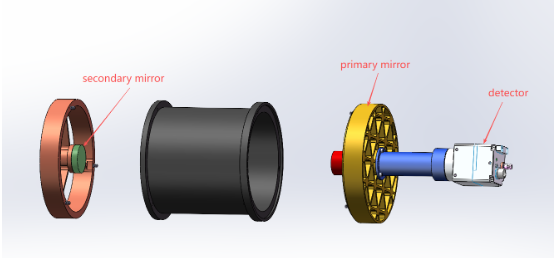
Image Credit: Avantier Inc.
Typical error contributors are:
Source: Avantier Inc.
| Error Source |
Optical Consequence |
6-DOF Compensation Role |
| Mirror decenter |
Coma, image shift, pupil misalignment |
X/Y correction |
| Axial displacement |
Defocus, back focal length error |
Z correction |
| Mirror tilt |
LOS error, coma, astigmatism |
Pitch/Yaw correction |
| Detector plane misalignment |
Field-dependent focus error |
Tip/tilt/Z correction |
| Thermal drift |
Time-varying wavefront error |
Closed-loop compensation |
| Deployment residual |
Segment phasing/alignment error |
Multi-axis correction |
| Structural creep |
Long-term boresight drift |
Periodic recalibration |
Required performance should be provided based on the mission error budget, for example:
- Translational resolution: 2 nm / 1 μm
- Angular resolution: 0.05 μrad / 0.01 arcsecond
- Repeatability: 5 nm / 0.1 μm
- Temperature stability: 0.2 nm/°C (0.01 μrad/°C)
- First resonance frequency: ≥ 80 Hz
- Stroke range: ± 5 mm / ± 2 degree
- Operational temperature range: 20 K-300 K
2. Why Space Telescopes Require Active 6-DOF Alignment
Alignment faults in ground-based optical assemblies are frequently fixed during integration and serviced on a recurring basis. Space telescopes do not have this luxury. Once launched, the telescope must endure a series of events that may alter its optical state:
- Initiate vibration and acoustic loading
- Release from launch limitations
- Deploy mirrors, booms, baffles, or sunshields
- Cool down to the working temperature
- Thermal cycling during orbital operations
- Long-term structural relaxation
- Spacecraft turbulence and jitter caused by reaction wheels
The challenge is keeping the telescope aligned after it has gone through all these mechanical and thermal phases.
This is when 6-DOF placement becomes crucial. It lets the telescope correct accumulated misalignments that passive mechanical design cannot fully remove.
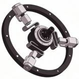
Cutway view of 6-DOF Positioning System. Image Credit: Avantier Inc.
3. From Kinematic Motion to Optical Consequence
For an optical engineer, the six degrees of freedom are less essential as mechanical definitions than as optical error sources. Translations and rotations are intimately related to wavefront and pointing errors:
- X/Y decentering can cause coma, pupil shift, field distortion, and detector registration errors
- Z displacement largely impacts focus, back focal length, and wavefront curvature
- Pitch/yaw inaccuracies can cause line-of-sight deviation, coma, and field-dependent aberrations
- Roll inaccuracy can impact detector orientation, polarization reference frames, and picture registration
A mirror tilt of 0.1 μrad can result in a LOS deviation of around 0.1 μrad, depending on the optical arrangement.
At an orbital altitude of 1500 km, this translates into a ground-projected aiming inaccuracy of around 0.15 m. This connection explains why 6-DOF tolerances cannot be evaluated only mechanically. They must be examined using optical sensitivity analysis.
4. 6-DOF Mechanisms Used in Space Telescope Architectures
4.1 Hexapod Platforms
Hexapod mechanisms are commonly utilized for full six-axis adjustment with high stiffness and predictable kinematics. They can be used to position secondary mirrors, align segments, calibrate interferometers, and adjust optical benches.
The primary advantages are:
- Full 6-axis positioning
- High stiffness-to-mass ratio
- Compact mechanical architecture
- Good repeatability
- Compatible with closed-loop sensing
Key specification placeholders:
- Translational stroke: ± 4 mm
- Rotational stroke: ± 1.5 deg
- Translational resolution: 1 nm
- Angular resolution: 0.02 μrad / 0.004 arcsec
- Repeatability: 3 nm / 0.05 μm
- Axial stiffness: 1200 N/mm
- Lateral stiffness: 750 N/mm
- First natural frequency: 95 Hz
- Operating temperature: 15 K to 320 K
The essential design challenge is not only positioning precision, but also the platform's ability to retain alignment under heat gradients, launch limitations, and structural stress courses without introducing excessive parasitic motion.
4.2 Fine Steering Mirrors
Fine steering mirrors target a particular aspect of the error budget. They are often designed for high-bandwidth pointing stability and jitter reduction, rather than large-stroke alignment.
They are especially important when residual spacecraft disturbance would otherwise decrease image quality during extended exposures. The typical disruption sources include:
- Reaction wheel jitter
- Vibration from the cryocooler
- Solar pressure changes
- Micro-vibration in structural components
- Attitude-control residual error
Key specification placeholders:
- Angular range: ± 250 μrad / ± 0.25 mrad
- Angular resolution: 2 nrad / 0.002 μrad
- Bandwidth: ≥ 1200 Hz
- Settling time: < 0.8 ms
- Mirror diameter: 60 mm
- Wavefront distortion contribution: < 5 nm RMS
- Pointing stability contribution: 0.001 arcsec / 1 mas
For space telescopes, FSM performance should be measured by actuator bandwidth and its contribution to residual line-of-sight stability and wavefront error.
4.3 Segmented Mirror Actuation
Large deployable telescopes provide another level of 6-DOF complication. To accomplish phasing and global wavefront control, each mirror segment may require piston, tip, tilt, and, in certain cases, extra degrees of correction.
In this instance, 6-DOF control is no longer a single-mechanism issue. It becomes a distributed optical control issue that includes:
- Segment placement
- Phasing in segments
- Wavefront sensing
- Updating structural models
- Compensating for thermal distortion
- Optical correction is closed-loop
Specification placeholders:
- Segment piston range: ± 50 μm / 0.05 mm
- Segment tip/tilt range: ± 300 μrad
- Phasing accuracy: < 12 nm RMS
- Wavefront sensing accuracy: < 8 nm RMS
- Segment-to-segment stability: < 15 nm over 24 hours
- Thermal drift allowance: 22 nm over ΔT = 10 K
5. Closed-Loop Control: Sensor, Actuator, Optical Feedback
The metrology and control loop of a space-qualified 6-DOF system is the most important component. The control architecture often includes:
- Position sensors to provide local mechanism feedback
- Optical state feedback via wavefront sensing
- Use star trackers or guide sensors for pointing reference
- Thermal sensors used for model-based correction
- Actuators include piezo stages, voice coils, flexure mechanisms, and motorized struts
The primary contrast is between mechanical closed-loop and optical closed-loop control.
Although a mechanism can return to its commanded location with high repeatability, the optical system may still undergo wavefront drift owing to heat gradients, structural deformation, or mirror figure change. For high-end space optics, the control loop must eventually revolve around optical performance, not just encoder position.
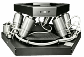
Six-degree-of-freedom platform system. Image Credit: Avantier Inc.
6. Thermal Stability: The Hidden Driver of 6-DOF Design
Thermal behavior is frequently the primary long-term alignment problem.
A telescope may be precisely aligned at room temperature during terrestrial integration, but subsequently undergo considerable alignment change during cooling or orbital thermal cycling.
This is especially important for cryogenic infrared telescopes, where structural contraction and material CTE mismatch can move optical components in many degrees of freedom.
Important thermal design elements include:
- Matching CTE of mirror, mount, and actuator
- Thermal gradients on the optical bench
- Actuator performance at low temperatures
- Friction or lubrication under vacuum
- Sensor drifts with temperature
- Thermal hysteresis occurs after repeated cycles
Specification placeholders:
- Operating temperature: 38 K
- Survival temperature: 12 K to 340 K
- Allowable thermal drift: 0.3 nm/K or 0.015 μrad/K
- Alignment stability after thermal cycle: < 0.08 μm / 0.003 arcsec
- Number of qualification cycles: ≥ 120 cycles
- Residual wavefront error after cooldown: < 18 nm RMS
For this reason, 6-DOF mechanisms for space telescopes should be regarded as thermo-optomechanical subsystems rather than isolated motion stages.
7. Ground-Alignment Example: Motorized 6-DOF Positioning of a Compact RC Telescope
This example shows a motorized 6-DOF stage used only for ground integration, not an on-orbit active correction system.
The optical performance of a tiny Ritchey-Chrétien telescope with an effective focal length over 1800 mm and a total system length of around 305 mm was extremely sensitive to decenter, tilt, and axial spacing errors.
The alignment procedure involved:
- Coarse mechanical positioning: Used mechanical datums to position the entire optical system
- Wavefront-guided fine alignment: Used a motorized 6-DOF stage to fine-tune alignment based on interferometric wavefront performance
- Final mechanical fixation: After achieving the desired optical performance, the assembly was mechanically fastened in its final alignment
- Post-alignment verification: Verified telescope alignment using thermal cycling and 10 g random vibration testing, then re-evaluated optical performance
This example demonstrates how wavefront-guided 6-DOF positioning may directly link mechanical adjustment to system-level optical performance during telescope assembly.
8. JWST as a Representative Case
The James Webb Space Telescope demonstrates why 6-DOF control is critical in current space optics.
JWST was launched in a folded structure, deployed into orbit, cooled to cryogenic temperatures, and then oriented for optimal optical performance. This procedure necessitated adjustment for deployment residuals, thermal contraction, segment location errors, and wavefront phasing problems.
The main takeaway is not just that JWST uses precise actuators. The main takeaway is that big deployable telescopes require active alignment designs from the start of the design process.
Without multi-axis adjustment, the telescope would have to rely solely on passive deployment precision and structural stability, which is not feasible for large-aperture space systems.
9. Design Implications for Future Space Telescopes
Future space telescopes are expected to increase 6-DOF needs even further. Larger apertures, formation-flying interferometers, deployable segmented mirrors, high-contrast imaging, and planetary observations all need more precise alignment and wavefront stability.
This leads to various design implications:
- Optical tolerance analysis must account for 6-DOF systems from the outset
- Motion parameters should be based on wavefront and LOS budgets, not chosen separately
- Thermal drift should be considered a first-order design driver
- Ground calibration must include launch, installation, and cooldown phases
- Closed-loop optical feedback will become more significant
- Evaluate mechanism stiffness and dynamic behavior together with the spacecraft disturbance spectrum
In other words, 6-DOF positioning is transitioning from an auxiliary alignment function to a key enabling technology for future space telescopes.
The Future of 6-DOF Positioning Systems for Active Optics and Wavefront Stability
For current space telescopes, 6-DOF control is more than just a mechanical advantage. It links optical design goals to in-orbit performance.
By correcting for manufacturing tolerances, integration residuals, deployment uncertainty, structural drift, thermal deformation, and pointing disturbance, 6-DOF positioning solutions directly enhance wavefront stability, line-of-sight precision, and long-term observation reliability.
Future missions will require bigger apertures, lighter structures, and tighter wavefront budgets; therefore, 6-DOF mechanisms will play an increasingly important role in space telescope design, fabrication, calibration, and operation.

This information has been sourced, reviewed, and adapted from materials provided by Avantier Inc.
For more information on this source, please visit Avantier Inc.