The application of in situ hybridization (ISH) has developed from short term, generic isotopic techniques, to highly specialized, long term, multicolor Fluorescent-ISH probe assays (FISH).
Advancements in microscopes, optics, cameras, data handling, and filter technology by software have enabled cost-efficient FISH systems to be attainable for the majority of researchers.
The application of mFISH (multiplex-FISH), in combination with the improvements in digital imaging microscopy, has significantly enhanced the capabilities for non-isotopic identification and the analysis of several nucleic acid sequences in genes and chromosomes1.
Filters and Fluorescent Imaging
The epifluorescent path (illumination from above) is followed by the fluorescence illuminator to the specimen in an upright microscope.
The filter blocks are housed in the pathway, which includes the dichroic mirror, emission, and excitation filters, which work to strongly enhance the contrast and brightness of the imaged specimens, even when several fluorochromes are being utilized.
Figure 1 shows the standard arrangement of the fluorescence illuminator on an upright microscope.
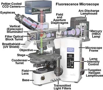
Figure 1.
The main elements in the episcopic (reflected illumination) pathway are comprised of the source of light (in this example, a Mercury arc lamp), a sequence of lenses that work to focus the light, and correct for optical deviations when the beam moves toward the filters.
Diaphragms are also present, which establish effective and balanced illumination of the specimen, and the filter turret, where the filter sets are located.
The diagram schematically details how the broadband excitation light from the source of light is carefully filtered to transmit the green component exclusively by using the excitation filter in the turret, which the dichromatic mirror reflects in turn to the specimen.
Through the objective lens, the red fluorescence emission is transmitted back through the mirror and is filtered again by the emission filter prior to visualization by camera or eye.
Figure 2 demonstrates an exploded view of the filter cube. The excitation filter is presented in yellow, and the emission filter is shown in red to portray a standard band-pass Texas Red filter set.
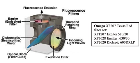
Figure 2.
Filter Descriptions
There are multiple ways to describe band-pass filters. The most popular is the Full Width Half Maximum (FWHM) and Center Wavelength (CWL) nomenclature, or alternatively, by nominal cut-on and cut-off wavelengths.
In the former, the exciter in Figure 2 is shown as a 580/20, or a filter with a FWHM of 20 nm and a nominal CWL of 580 nm. The half maximum value is captured at the transmission value, where the filter has attained 50% of its maximum value (Figure 3, Left).
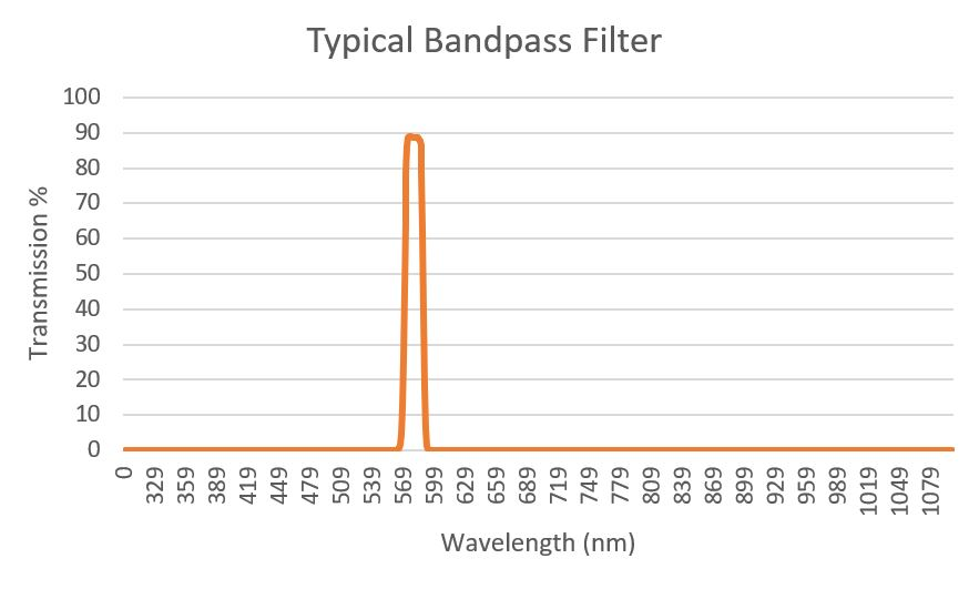
Figure 3.
In the latter plan, the filter can be detailed as having a cut-on of 570nm and a cut-off of 590 nm, while no CWL is specified.
The cut-on explains the change from attenuation to transmission of the filter across an axis of growing wavelengths. The cut-off outlines the change from transmission back to attenuation. Both values specify the 50% point of total transmission.
Cut-on and cut-off values are additionally utilized to explain two categories of filters called long pass (or high pass) filters (shown in Figure 4) and short pass (or low pass) filters (shown in Figure 5).
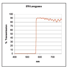
Figure 4.
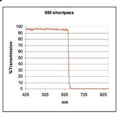
Figure 5.
A long pass filter is produced to absorb and/or reflect light in a particular spectral region. It goes into transmission at the cut-on value (570 nm in this example) and transmits light greater than this across a wide wavelength range.
The reverse is true of short pass filters; they block the wavelengths of light that are longer than the cut-off value at a particular distance and transmit shorter wavelengths.
It is important to note that these transmission and reflection regions do not go on indefinitely, but are restricted by the characteristics of the coating design, the physical properties of light, and coating chemicals.
In order to minimize the spectral bleedthrough of very closely spaced fluors in multicolor labeling schemes, specialized narrow band filter sets are needed.
Specialized Filters for FISH and mFISH
Special considerations regarding the arrangement of the filter blocks in the microscope turret are necessary when imaging several fluorescent probes. One technique is the use of separate filter cubes for every probe in the specimen.
This is a successful method for 6 color viewing (six being the average number of filter positions in the majority of upright research microscopes) because the effective spectral isolation of the various probe species can be acquired through attentive filter design.
This organization additionally decreases the possibility of bleaching the probes as it illuminates only one fluorescent species at a time.
A possible limitation of this setup is image registration shifts as a result of tiny filter misalignments. This shift creates deviation in the beam that is small but can be identified when changing between multiple different filter cubes.
The emission filter and the dichroic mirror are the imaging components of the filter cube and are the two elements which can cause this effect.
A different technique is to use individual multiband dichroic mirrors and emission filters and to exclude the exciter filters either in a filter wheel or an external slider.
The exclusion will maintain the image registration and decrease mechanical vibrations, but the trade-offs are decreased fluorescent brightness, restrictions on the number of different probes that can be separated, and decreased sensitivity and dynamic range as a result of the color CCD camera required.
Fluorescent microscopes are normally supplied with standard filter cubes for the popular DAPI stain, TRITC, FITC, and Texas Red fluors. Average filter sets tend to use wideband excitation and emission filters (sometimes utilizing long pass emission filters) the most, to offer optimum brightness.
When applying FISH, these standard sets can perform effectively for 2, 3, and 4 color labeling, but spectral bleedthrough can quickly become a challenge. For example, FITC is moderately visualized via the Cy3 filter, and Cy3.5 can be observed through the Cy5 filter2.
Figure 6 shows five individual labeled chromosome pairs; the arrows in the top, middle, and bottom left images demonstrate the crosstalk between channels. An overlaid and pseudo-colored image of the series is shown in the bottom right panel.
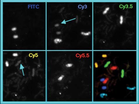
Figure 6.
In order to mitigate the spectral bleedthrough of the fluors in multicolor labeling schemes that are positioned very close together, specialized narrow band filter sets are required.
Emission filters of 20 to 40 nm and exciter filters of 10 to 20 nm enable the specificity required to attain the level of spectral resolution and sensitivity necessary in mFISH.
Figure 7 demonstrates a standard wide band FITC filter set overlaid on the emission and excitation peaks of FITC and Cy3.
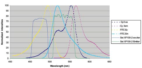
Figure 7.
While the filters are configured to cover a significant region under the emission and absorption curves, there is a strong overlap with both the emission and excitation curves of Cy3, leading to the contamination of the FITC channel by Cy3.
Figure 8 shows a solution to this. The emission and excitation bands have been narrowed to enhance the spectral resolution of FITC from Cy3, particularly in the emission band. By restricting the red edge of the emission filter, a decrease in the region under the emission curve of the Cy3 dye of around 4-fold is attained.
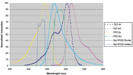
Figure 8.
The inclusion of narrow band, steep-edged filters in the design system widens the spectral window for adding several fluorescent probes without the expense of adding emission bleed between fluors.
This process can be observed in Figure 9, which shows three fluors that have been successfully divided inside of a spectral window of less than 300 nm. A fourth dye, like Cy 3.5, could be included in this strategy in the 570 to 620 nm region but is excluded here in order to decrease congestion.
Due to the demands on the filters utilized for mFISH, it is a requirement to offer a particular category of products that are matched together to make the best use of the bandwidth available for each mFISH fluor.
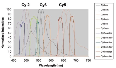
Figure 9.
Table 1 demonstrates the Omega Optical series of filter sets for the more commonly used fluors in mFISH, as well as detailing the emission and excitation filter bandwidths. All are single fluor sets apart from XF231 and 232, which utilized single exciters for each fluor and triple band emission and dichroic filters.
This system reduces stage movement and registration shift through only one requirement, which is that an external filter slider or wheel should be moved to excite the various dyes while the multiband emission and dichroic filters are held in a fixed position in the microscope turret.
Table 1.
| Set Name |
Fluorophores |
Filters |
| XF06 |
DAPI, AMCA |
Exciter: 365/50 |
Dichroic: 400DCLP |
Emitter: 450/65 |
| XF201 |
DEAC |
Exciter: 436/8 |
Dichroic: 455DRLP |
Emitter: 480/30 |
| XF202 |
FITC, Cy2 |
Exciter: 485/20 |
Dichroic: 505DRLP |
Emitter: 530/30 |
| XF203 |
Alexa 532 |
Exciter: 520/18 |
Dichroic: 545DRLP |
Emitter: 565/20 |
| XF204 |
Cy3, TRITC, Alexa 546 |
Exciter: 546/10 |
Dichroic: 555DRLP |
Emitter: 580/30 |
| XF206 |
Cy3.5 |
Exciter: 572/15 |
Dichroic: 590DRLP |
Emitter: 620/35 |
| XF207 |
Texas Red,
Alexa 594 |
Exciter: 580/20 |
Dichroic: 600DRLP |
Emitter: 630/30 |
| XF208 |
Cy5, Alexa 647 |
Exciter: 640/20 |
Dichroic: 650DRLP |
Emitter: 682/22 |
| XF210 |
Cy5.5 |
Exciter: 665/32 |
Dichroic: 692DRLP |
Emitter: 710/40 |
| XF231 |
DAPI/ FITC/ TRITC |
Single exciters for each dye can be housed in external filter wheel, triple band dichroic and emitters housed in filter holder |
| XF232 |
DAPI/FITC/ |
Texas Red Single exciters for each dye can be housed in external filter wheel, triple band dichroic and emitters housed in filter holder |
A proper combination of filters, dyes, imaging hardware, and software is desirous for obtaining the resolution and contrast necessary for accurate image capture and analysis.
Along with the use of specialized filter sets for mFISH procedures, additional features of the filters which have enhanced image quality are broadband AR (anti-reflection) polished substrates and coatings.
The AR coating can enhance transmission by decreasing secondary surface reflections at glass interfaces. This optimization can produce up to a 7% increase in filter throughput3.
AR coatings on dichroic mirrors and emission filters also prevent the ‘ghost image’ that can sometimes be observed in optical pathways with several reflective surfaces
Polished substrates are characteristics mostly seen on the dichroic and emission filters. When the glass substrate is exposed, on which the filter is made in a two-sided polishing technique, the substrate attains a high level of ‘parallelism’ or even thickness.
This technique has the impact of decreasing strong beam deviation in the transmitted image, which produces minimal registration shifts when quickly changing between filter sets.
Conclusion
The methods of FISH and mFISH used in combination with the automated digital imaging capabilities and resolving power of the fluorescence microscope provide an effective combination of benefits.
Its advantages will prove useful to many fields within biology, from primary research to cytogenetics, pathology, cancer research, and the detection of prenatal diseases.
In the fluorescence microscope, selective consideration of the system components and sample is required to determine the most effective filters for probe detection.
The use of multiband emission and dichroic filters in a stationary turret with single exciters in an external filter wheel or slider can offer the almost simultaneous detection of probes with no registration shift
There are likely some compromises to be made in the color balance difficulty, reduced resolution, and overall brightness of the color CCD camera.
If spectral resolution, minimal photobleaching, and sensitivity are main concerns, single narrow band filters sets with black and white CCD camera detection is the ideal choice.
Image registration shifts are reduced in contemporary filters through the use of polished substrates and are almost eliminated by utilizing filter sets produced to ‘zero shift’ specifications.
The optimization of the filters is also influenced by the number and type of fluorescent probes. It is possible to utilize conventional wide band-pass filter sets for a small number of probes with sufficient spectral separation.
Where five or six probes are being employed in a protocol, it is a requirement to use dye-specific narrow band filter sets to decrease spectral bleedthrough
As techniques in FISH and mFISH on the fluorescent microscope develop, so must the hardware and software being used in decoding the information comprised in the specimen.
The correct combination of dyes, filters, imaging software, and hardware is essential for acquiring the required contrast and resolution to capture and analyze images accurately.
Troubleshooting
If there is no image:
- Verify that the fluorescence light source is on and check the clarity of the light path. Light can normally be observed when it illuminates the sample unless it is less than 400 nm (DAPI excitation).
- Check that the image is being delivered to the correct camera, eyepiece, or port.
- Verify that the proper filter block is in position for the desired fluor.
- If the emission of the desired fluor is greater than around 670 nm (Cy5), then it will not be seen by most eyes. If it cannot be seen by the camera, ensure that there is no IR blocking filter in the camera.
If the image has high bleedthrough from different fluors:
- Ensure that the filter set is intended for single dye usage and that a long pass emission filter or wide band-pass filter set is not being used.
Glossary
- Anti-reflection coating: An optical thin film interference coating created to reduce reflections that happen when light moves from one channel into another.
- Dichroic Mirror: Selectively reflecting and/or transmitting light in relation to its wavelength. A long pass dichroic transmits a wide spectral range while quickly reflecting shorter wavelengths across an alternate optical channel.
References and Further Reading
- Brenner, M., Dunlay, T., & Davidson, M. (n.d.). Fluorescence in situ hybridization: Hardware and software implications in the research laboratory. Retrieved October 7, 2008
- Henegariu, O. 2001. Multicolor FISH. Retrieved October 8, 2008
- Johnson, B. 2006. Anti-Reflection Coatings. Omega Optical Application Note.
Acknowledgments
Produced from materials originally authored by Dan Osborn from Omega Optical, Inc.

This information has been sourced, reviewed and adapted from materials provided by Omega Optical, Inc.
For more information on this source, please visit Omega Optical, Inc.