Many factors impact the cost of confocal microscopy systems. When selecting and purchasing a microscope, it is important to consider the complexity of the instrumentation and the capabilities it provides.
More complex configurations of confocal, widefield, spinning disk, or TIRF systems include higher associated costs. A potential buyer must navigate a myriad of options around highly sensitive detectors, multiple imaging modes, multimodality and simultaneous multicolor imaging.
This article explores these factors and considerations, as well as providing an overview of the fundamental hardware of confocal microscopes and an outline of some of the available choices when selecting a confocal microscope system for a specific application.
It is important to have an overall understanding of how a spinning disk confocal system functions, as well as an awareness of systems with other imaging modalities; for example, TIRF and super-resolution.
While hardware costs are a key consideration, software options also affect the overall cost of a confocal microscope, including options included in the basic software package and any extended software options. Before making a final choice of microscope, consideration should also be given to system servicing and longer term maintenance costs.
An extensive list of hardware, software and maintenance options is outlined below, designed to empower potential buyers to select the most suitable system while balancing performance, features and overall cost.
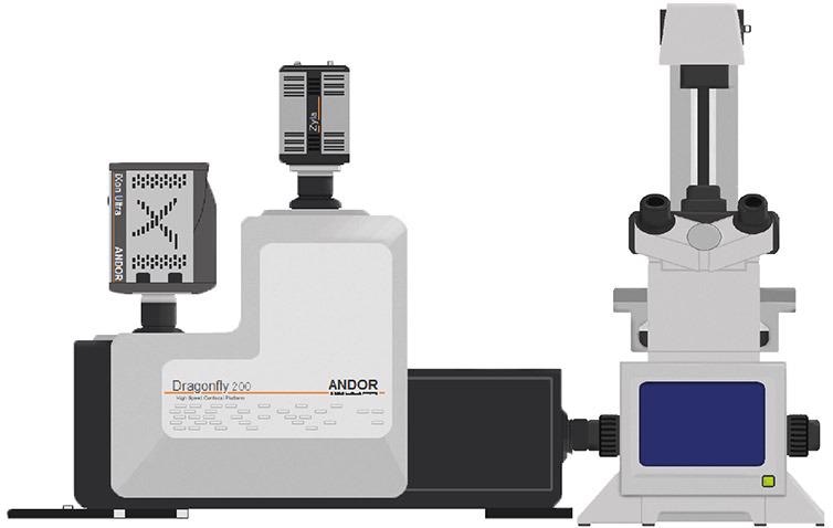
Figure 1. Schematic of Andor’s Dragonfly spinning disk system attached to an epifluorescence microscope. Image Credit: Andor Technology Ltd.
The Pinhole (Spinning Disk)
Users can select between single pinhole and dual pinhole options.
The pinhole's role is to discard out of focus light. A 40 µm pinhole is ideally suited to high magnifications (63X and 100X), while a 25 µm pinhole is a better choice for lower magnifications. A dual pinhole microscope will offer more versatility but will result in additional costs.
The choice of pinhole is pertinent when working with spinning disk confocal microscopes because this type of equipment has fixed pinhole size(s). Pinhole selection is not an issue for point scanner confocal microscopes.
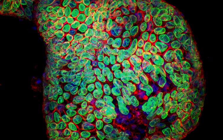
Figure 2. Organoid image. Image acquired with Dragonfly spinning disk confocal system using 25 um pinhole. Image courtesy of Dr Luke Boulter, MRC Human Genetics Unit, IGMM, University of Edinburgh.
Extra Magnification
Additional magnification in front of the camera port facilitates acquisition under Nyquist criteria for cameras with pixel sizes higher than 6.5 µm. While larger pixel sizes gather more light, these do not accommodate Nyquist at lower magnifications.
Extra magnification may be achieved by using a fixed or motorized lens that enables switching. Being able to acquire under Nyquist or strict Nyquist criteria is a key requirement for both deconvolution and super-resolution microscopy.
Various microscope companies offer a diverse range of extra magnification options, and many of these can be used in conjunction with the camera in order to acquire under Nyquist conditions.
Dichroics
Dichroics can be single or multiple band pass, and users can select between, single, double, triple, quad and band pass options. Multiple band pass dichroics enable simultaneous multicolor imaging, while band pass dichroics are a good option for systems employing dual camera acquisition modes.
Using various dichroics improves the flexibility of acquisitions, and it is possible to employ either a motorized or manual dichroic switch.
A Dragonfly spinning disk system supports a total of four dichroics, which are interchangeable via a motorized switch.
Emission Filters
Users should select an appropriate number of single band pass or multiple band pass emission filters.
Multiple band pass emission filters allow faster multicolor imaging, but exactly the right filters and fluorochromes must be used to ensure that the resulting image does not exhibit bleed through between channels. Single band pass emission filters, however, considerably minimize the risk of bleed through.
The number of emission filters selected will directly impact the number of channels that may be acquired during a multicolor imaging experiment.
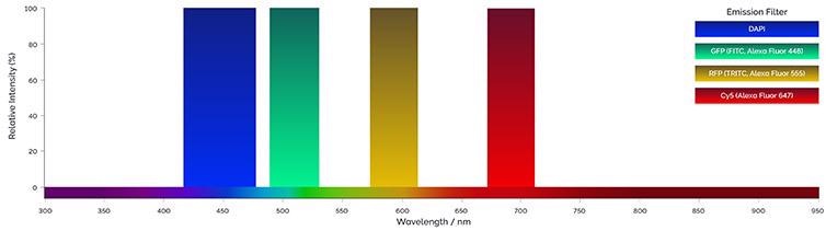
Figure 3. Example of emission filters bandpass. Single or multiple band pass filters can be used to acquire multicolor images. Image Credit: Andor Technology Ltd.
Laser Unit
Users should consider how many lasers a multiple laser line source can accommodate, as well as the laser power supported, and the range of laser wavelengths supported.
Lasers
Users should consider the number of lasers used, and whether these are to be single mode or multimode fiber. The lasers' power should also be considered.
The laser quantity and their wavelengths will directly affect the experimental design and number of acquirable channels.
A laser unit able to accommodate near infrared (NIR) wavelengths (>650 nm) offers specific experimental advantages - these lasers allow for deeper penetration into the sample while being useful for live imaging experiments due to their less energetic nature.
Single mode fiber offers a robust point source for diffraction limited point scanning, but single mode fiber is not suitable for the efficient coupling or transmission of longer wavelengths.
Dragonfly's multimode optical fiber and patented Borealis™ illumination system supports excitation wavelengths of 400–800 nm and detection wavelengths of 425–850 nm. Higher laser powers might be necessary for specific applications; for example, laser ablation or Super-Resolution (STORM) experiments.
Certain experimental requirements may influence requirements around the type, number, powers, and laser wavelengths. This will in turn impact laser choices, directly affecting the complexity and ultimately the cost of the system.
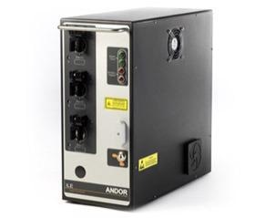
Figure 4. Integrated Laser Engine. Image shows Andor´s Integrated laser Engine, that supports up to 8 laser lines and accommodates visible to the NIR range lasers in a single unit. Image Credit: Andor Technology Ltd.
Detectors
Users should select between photomultiplier tubes (PMTs) and hybrid detectors, or they may wish to employ camera-based detectors (sCMOS and EMCCDs). There are key differences between PMT and sCMOS or EMCCD detector technology.
Point scanners typically utilize photomultiplier tubes (PMT) and hybrid detectors, while multipoint confocals generally employ camera-based detectors.
A number of parameters can be used to evaluate the performance of a scientific detector. These include:
Quantum efficiency (QE) – a representation of a detector's capacity to efficiently convert a photon to an electron. A higher QE represents a more sensitive detector; for example, 50% QE illustrates that half of the photons are converted to electrons.
Dark current – a measurement of the noise generated by the sensor itself in the absence of any signal. This is expressed as electrons (e-)/pixel/sec. Lower dark current values are better, and because this increases over time it becomes increasingly important with longer exposure times. The dark current can be reduced by camera cooling.
Read noise - created as the camera electronics convert the electrons from analog to a digital signal, and this digital signal is then amplified. A lower read noise value is desirable because this sets the camera's noise floor and defines its capacity to detect a signal of interest.
Cooling – dark current can be reduced by cooling the camera sensor. This cooling may be passive (for example, heat exchange from camera body to ambient air), or the camera can be air cooled using a fan (though this may act as a vibration source). Water cooling is available on some camera models and remains the most effective cooling option, particularly for vibration-sensitive measurements requiring high frame rates at high magnification, or localization microscopy. Effective cooling also reduces the risk of 'hot' or high noise pixels that could impede image quality, particularly in image stacks or 3D volumes.
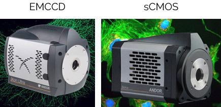
Figure 5. Image of iXon Ultra 888 EMCCD and Sona 4.2B-6 sCMOS. Image Credit: Andor Technology Ltd.
Camera-based detectors are more sensitive and better at capturing photons than PMT and hybrid detectors.
The QE of a PMT and hybrid detector is a maximum of 45%, while the QE of sCMOS and EMCCDs is typically between 80% and 95%. EMCCDs and sCMOS detectors also offer lower dark current PMTs: EMCCDS (<0.001 e-), sCMOS (<1 e-) and PMTs (approximately 2 e-).
PMTs rapidly became established as market leading technology due to their lack of read noise, but contemporary camera technologies also offer low read noise. It is possible to achieve <1 e- effective read noise for EMCCDs using "EM gain", and between 1.1 and 1.6 e- for sCMOS models.
Overall camera-based detectors (EMCCDs and sCMOS) deliver much higher sensitivity versus PMT and hybrid detectors.
Cameras
Camera options typically include sCMOS, EMCCD and multiple camera systems.
Both sCMOS and EMCCD options offer have relative advantages and disadvantages depending on experimental requirements. sCMOS sensors' architecture increases experimental productivity and throughput due to its faster speeds and image acquisition with larger fields of view.
Some sCMOS detectors offer ultra-fast imaging and a 6.5 µm pixel size, highly suited to acquisition under the typical magnifications outlined in Nyquist conditions. Overall, sCMOS represents a good option for most common imaging applications.
EMCCDs offer improved sensitivity, making them the best choice for very low light imaging conditions or very faint signals. EMCCD cameras' very low dark current also makes them better suited to long exposure applications; for example, luminescence studies.
A large number of spinning disk confocal systems can work with two cameras. Even when system two cameras are not required, it is advisable to aim for a system that can accommodate a second camera; therefore affording users the freedom to accommodate future experimental requirements. The use of two cameras on a confocal system allows for increased speed, flexibility, and simultaneous multicolor acquisition.
Example Experimental Setup
Simultaneous double color imaging is possible in systems where an sCMOS's cameras pixel size can be binned to match the EMCCD, and chip sizes of each camera matches; for example, an EMCCD camera with a 13 µm pixel matches a 6.5 µm pixel of an sCMOS camera when 2x2 binning is used.
This example system would also combine sCMOS' large FOV and smaller pixel size and the very low light imaging capabilities of the EMCCD.
The number of cameras selected and their specifications will influence the microscopy system's overall cost. It should be noted that improvements in camera technology facilitate modular upgrades over time, and the system's imaging performance can often be improved by moving to the latest detector technology.
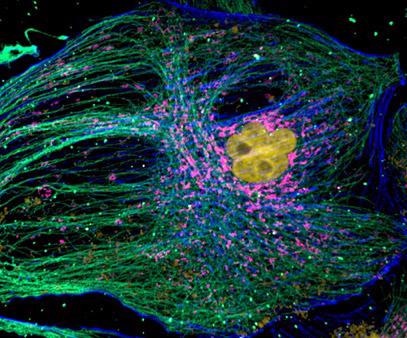
Figure 6. Mammalian cell cytoskeleton. Image acquired with Dragonfly spinning disk confocal microscope using an iXon 888 EMCCD camera. Image courtesy of Hao Hui Wen (Dr. Sun Yu Jie Lab), Peking University.
Microscope Stand
Various brands of microscope stand are available, and these can be either upright or inverted.
Different brands of microscope stand offer different options. One critical, and often overlooked issue is how ergonomic the stand is. Users must remain safe and comfortable as they spend many hours working on the microscope, acquiring and assembling a system. Users' comfort can also impact their health and productivity.
A choice will need to be made between an upright or an inverted stand. This will largely depend on the type of experiments performed; for example, electrophysiology experiments and intra-vital experiments like live blood vessel imaging typically necessitate an upright microscope stand. Mammalian live-cell imaging is generally performed using an inverted stand, however.
Users must consider the anticipated nature of their experiments, selecting the type of microscope stand accordingly.
The microscope stand's number of ports is also an important factor. Questions should be asked around whether other imaging, photostimulation, or optical devices must be attached to the microscope, either currently or in the future. For example, if the user plans to add other optical components to the microscope stand, a double-deck microscope should be selected.
A double-deck microscope stand may cost slightly more, but it will allow the user to keep their options open for future application needs. Using a double-deck microscope alongside a photostimulation device will also ensure an improved user experience for sample visualization. It is also possible to attach a camera for other imaging applications; for example, combining bioluminescence and fluorescence imaging.
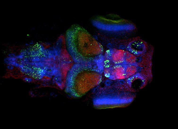
Figure 7. Neural system in Zebrafish larvae. Image acquired with Dragonfly spinning disk microscope using an inverted microscope stand. Simultaneous acquisition with two Zyla sCMOS cameras, band pass dichroic 25 um pinhole, and single band pass emission filters. Image courtesy of Ruth Diez del Corral and Davide Accardi, Champalimaud Centre for the Unknown.
Microscope Stage
A choice should be made between a manual, motorized or XYZ precision (Piezo) microscope stand.
The microscope stage is a key factor – arguably the most important after the stand. A motorized stage will increase the device's cost, but this does increase productivity as the user can acquire multiple tiles on XYZ with a single click. A motorized stage also facilitates large area, multi-field, montage imaging – an ideal solution for large samples or intact tissues.
Experiments requiring XYZ acquisition may also benefit from a piezo-based stage. Piezo-controlled stages will increase costs, but these offer distinct advantages for certain experimental setups.
Piezo stages offer smooth movement with nanometer and sub-nanometer precision for 3D imaging, as well as excellent step and settle times and rapid scanning. If budgets allow, a piezo-controlled stage is a good option for experiments requiring rapid acquisition and high movement accuracy.
Microscope Objectives
The objective is an essential component of the microscope and must be carefully selected in line with application requirements. This is a challenging task due to the sheer number of available options at each magnification. First, users must select the microscope's number of objectives the microscope, and the desired magnifications.
The Numerical Aperture (NA) refers to an objective's ability to capture wider rays of light - a wider cone of light equates to higher resolution power, though higher NA objectives are expensive. The required resolution is a key consideration, with high-end applications like dSTORM or Total Internal Reflection Microscopy (TIRF) necessitating the use of objectives with extremely high NAs (>1,4).
The working distance of the objective is an application-specific requirement that must be taken into account. Long working distance objectives are key to visualizing some development processes and facilitating access to the sample when extra equipment is necessary; for example, micro-injection needles. A higher working distance results in a lower NA.
An objective's immersion media is also an important consideration. To maximize the collection of light rays while avoiding diffraction, an objective's immersion media should offer a refractive index as close as possible to the sample's immersion media.
Frequently used immersion media include silicon, oil, water, air and glycerol. Air objectives are typically cheaper, while immersion objectives are generally more expensive.
When selecting an objective for fluorescence imaging, it should be noted that not all objectives will transmit equally in all wavelengths. Extra care should be taken when considering optics for experiments making use of NIR and UV wavelengths. For example, imaging DAPI requires an objective that can transmit in the UV range; while imaging NIR wavelengths, requires an objective that can transmit at these wavelengths.
Aberrations triggered by light passing through the glass can be corrected in various objectives, but these corrections frequently involve additional costs.
Objectives can be achromat or plan-achromat, fluorite, plan-fluorite, apo-chromat and plan-apo-chromat.
Achromat are the most straightforward objectives, offering fewer corrections, while plan-apochromat offer more corrections in more wavelengths; correcting for field curvature, spherical aberration, and chromatic aberration.
'Plan' means that the objective has been corrected for field curvature - distortions hindering the proper focus of an object on a flat plane which in turn adversely affect image quality. Field curvature correction (Plan) objectives are a good option when budget constraints allow these to be purchased.
Spherical aberration means that the rays of light reaching an objective lens exhibit distortions around the edges. These are more curved and will not focus on the same plane as rays of light passing through the objective's center, resulting in a blurred image.
Achromat objectives correct spherical aberration for one wavelength, while fluorite objectives correct two or three wavelengths, and plan apochromat objectives correct three or four wavelengths.
Chromatic aberration is a failure to focus every wavelength on the same plane. Here, achromatic objectives correct two wavelengths, fluorite objectives correct two or three wavelengths, while plan apochromat objectives correct four or five wavelengths.
An objective's supported techniques should also be explored, because an objective is unlikely to support all imaging modalities. One objective can support multiple imaging modalities, however; for example: brightfield (BF), darkfield (DF), phase contrast (Ph), differential interference contrast (DIC), polarization (Pol), and fluorescence (Fl).
The final cost of each objective will be dependent on a combination of the parameters outlined here. Savings can be made by selecting a microscope stand with compatible objectives already available.
Transmitted Light
Users should be aware of a range of transmitted light techniques overlaid onto the confocal fluorescent image to provide an overview of tissue and cellular shape.
Brightfield is less expensive and requires less complex optics, but a large number of cells and tissues are almost invisible via this technique.
Phase contrast microscopy does enhance the visibility of transmitted light images, but many images will still feature a potentially distracting phase halo.
Differential interference contrast provides higher resolution and contrast, but DIC optics are complex and therefore more expensive than the brightfield or phase contrast options.
Depending on the transmitted light technique selected, a number of components may need to be purchased; for example, polarizers, phase plate rings, and specific objectives that can accommodate the transmitted light technique itself.
Incubator Chamber
An incubation chamber is an essential requirement for live imaging applications, and there are a diverse array of options available.
When considering applications and other options for the system (for example, the microscope stand, stage and microinjection devices), the primary goal should be to fully integrate the confocal system so that every component works together and is suitable for the desired applications.
In terms of incubators, users can choose between a stage top incubator or a bottom stage incubator able to match the slides or Petri dishes employed in the lab, or a large incubator that can warm up the whole system. This final option would likely comprise of a large incubator to warm up the system and a heated sample holder to enable higher accuracy for the samples.
Key considerations when selecting an incubator include its temperature range, accuracy, temperature stability over time, and capacity to be cooled to achieve lower temperatures.
A stage incubator may be transparent to allow for more operator comfort when working with the microscope, or black to prevent unwanted light from entering the imaging system. The stage incubator can also be combined with a CO2 incubator, should CO2 be a key requirement for the experiment.
More options added to the incubator will result in additional expense; for example, such an incubator allowing CO2 control will cost more than an incubator which can only control the temperature.
Microscope Table
Users must select between rigid, active, or passive tables.
A rigid table does not isolate the sample against vibration, though these can provide down to 1 µm resolution provided the construction is robust enough. More sensitive applications, therefore, require a high quality table able to absorb any vibrations caused by the surrounding environment.
Some applications – for example, STORM, SRRF-stream and TIRF - can only be performed using an anti-vibration table. These are also extremely beneficial for applications such as large tile imaging or time lapse imaging where matching acquired tiles or moving continuous frames is vital. The cost will vary depending on the table selected, typically in line with the level of vibration isolation that the table can offer.
As a general rule, resolutions offered by microscope tables are:
- Rigid: down to 1 µm
- Passive: down to 0.01 µm
- Active: down to 0.001 µm
It should be noted that these figures are indicative, and specific table specifications should be consulted prior to purchase.
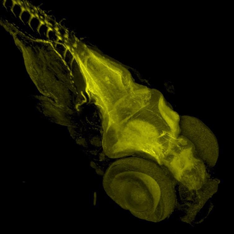
Figure 8. Zebrafish stained with Acetylated Tubulin. Image acquired with Dragonfly spinning disk microscope using a Sona 4.2B6 sCMOS camera. Image courtesy of Marco Campinho, Universidade do Algarve.
Other Light Sources
Users may opt to utilize LED, metal halide and xenon.
Confocal systems typically require the imaging area of the sample to be selected visually via the eyepieces. The user cannot use laser light sources for this, meaning that alternative options such as LED light sources, metal halide lamps, or xenon bulbs are required.
Current LED light sources can excite samples at a required wavelength, offering long lifespans and relatively low cost. LED light sources also deliver low energetic light, reducing phototoxicity and photobleaching when screening through the sample. These advantages have seen LED light sources all but replace their metal halide and xenon light counterparts.
The required number of wavelengths should also be considered, and it may be necessary to employ multiple LED lines in a system. The more wavelengths available to a system however, the more expensive the light source will be.
Super Resolution
A number of super resolution options are available, including SIM, STED, STORM, and SRRF-Stream+.
Many super-resolution techniques offer enhanced resolution by leveraging variable laser intensities, improved optics, and computer-based methods.
Where higher laser powers are needed for imaging, there is less chance the technique will be compatible with live cell super-resolution. More complex techniques require more sophisticated implementations, typically resulting in high associated costs.
SIM can provide resolution down to 100 nm while compatible with both live cell imaging and widefield microscopy. SIM can achieve speeds up to 1 frame per second and can be used with any fluorophore; but it does require the use of specialized optical components while delivering more power to the sample than conventional widefield methods. SIM requires a dedicated microscope, so this technique not generally found in a multimodal confocal system.
STED can provide resolution in the range of 40-50 nm. STED's optics are complex and expensive, limiting the accessibility of this technique. The super-resolved image is delivered instantly during STED acquisition and this technique does not require the use of computational image analysis. STED also requires a dedicated microscope, making it uncommon in a multimodal confocal system.
Single Molecule Localization Microscopy (SMLM) techniques including STORM, dSTORM, and PALM leverage the photoactivation of selected molecules to identify their location. Repeated excitation of a small number of molecules (103 to 104 times) will enable a super-resolved image to be delivered. STORM does necessitate high available computing power in order to analyze images, but no special optics are required – making STORM a more cost-effective option than STED or SIM.
SMLM technologies generally employ higher laser powers, making them incompatible with live cell imaging. STORM is a widefield technique that can be used in conjunction with TIRF illumination. SMLM techniques (PALM and STORM) offer the highest resolution of super-resolution technologies and can achieve up to 10 nm laterally.
SRRF (Super Resolution Radial Fluctuations) and Andor's SRRF-Stream+ are both compatible with live cell imaging. SRRF-stream+ is a cost-effective camera-based method able to achieve super-resolution while providing 100 nm of lateral resolution. Higher resolution is achievable under some imaging conditions, and this technique does not require complex sample preparation steps. It is also able to deliver super-resolved images deep inside cells and tissues.
Resolution improvements provided by SRRF-Stream+ are similar to those achievable via SIM, but SRRF-Stream+ offers a simpler, more cost-effective camera-based means of improving an existing system's resolution.
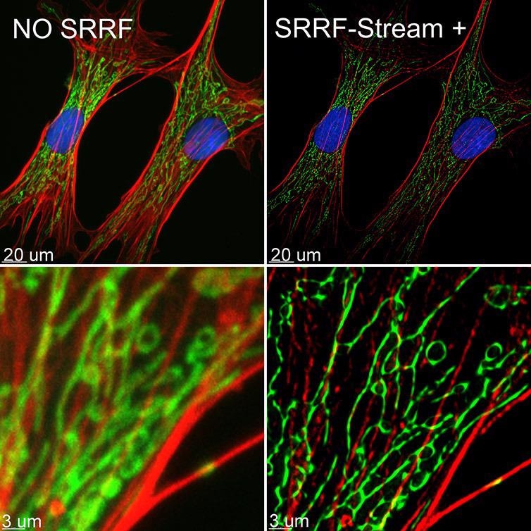
Figure 9. BPA cells stained with phalloidin (red), mitotracker (green) and DAPI (blue) where imaged with Ixon 888 Ultra in confocal mode (no SRRF) and confocal mode with SRRF-stream+. Image acquired with Dragonfly spinning disk microscope using an Ixon 888 EMCCD camera. Image by Claudia Florindo, Andor, An Oxford Instruments Company, Belfast, UK
3D-STORM
Where there is a requirement to ensure the maximum resolution available via dSTORM, equipment capable of delivering 3D super-resolved images is an ideal option.
An astigmatic lens causes a distortion in the PDF, offering an elegant means of delivering 3D-dSTORM images. The PSF distortion encodes a differential positive and negative axial offset in X and Y dimensions, and this can be translated into an axial position which enables the creation of a 3D super-resolved image.
Andor Dragonfly features an integrated astigmatic lens option, suitable for 3D-dSTORM image acquisition. It is advisable to ascertain if 3D-dSTORM is required at the point of purchase. This option can be added after purchase, but this requires the system to be returned to the factory – resulting in equipment downtime and increased costs.
The Point Spread Function (PFS) represents an imaging system's response to a point object. As light passes through an optical system (lens and other imaging components), this light will be distorted due to the properties of the optical components of the system.
An infinitesimal point will not appear as a point if the image is blurred, and the resulting image is considered convoluted. Because the PSF is identical in all imaging space and all objects being imaged, a mathematical process can be used to revert the blur – deconvolution, effectively removing any 'fog' and showing the true object with improved clarity.
TIRF
Users should select between single color, dual-color, simultaneous TIRF, and simultaneous dual color TIRF.
A total internal reflection (TIRF) microscope enables the acquisition of highly detailed images of an object near to the sample surface. TIRF microscopes are built to force the light to reach the edge of the slide in TIRF angle, despite obstacles being in the light path. TIRF will allow imaging up to a maximum of 100-200 nm from the top of the sample, but one effect of this approach to illumination is that images may only be acquired in a very thin boundary at the glass/water interface.
The high resolution afforded by a TIRF system makes this a good option for single-molecule imaging, also meaning that TIRF imaging can be combined with dSTORM acquisition.
TIRF offers a robust solution for analyzing live cell events at the cell membrane boundary or at the cell surface; for example, vesicle trafficking, membrane dynamics, endocytosis, and exocytosis.
Where TIRF is required, consideration should be given to whether software can correct the penetration depth angle and whether dual color TIRF be performed with adjusted penetration angles per wavelength.
A dedicated TIRF system will be more cost-effective than a multimodal confocal system, but this system will be limited to TIRF imaging. Should TIRF be required as part of multimodal confocal system, this functionality is provided by Andor's Dragonfly system.
Multimodal System
Many research laboratories and core facilities can benefit from employing a multimodal system that delivers high-quality images in all modalities. Imaging requirements for core facilities are extensive and varied; and a multimodal system will provide several imaging options allowing several different imaging projects to be run in parallel.
As research results and discoveries progress in research labs, further imaging approaches may be required. A multimodal system will offer the extra versatility required in these scenarios, without the need to purchase additional equipment.
Widefield systems are typically rapid and gentle in terms of their treatment of samples, making them a sensible choice for live imaging of fixed cells or thin organisms; for example, yeast, bacteria, microalgae and monolayer cells. Widefield systems do not offer optical sectioning, however, making them unsuitable for use with thick and highly scattering samples.
A confocal system is a microscope able to perform optical sectioning. These systems use the pinhole to discard out-of-focus light. There are two types of confocal microscope: point scanning confocals (in which a single pinhole discards the out of focus light) and multipoint confocals (spinning disks – in which multiple pinholes discard the out-of-focus light.
Single point confocals offer the capacity to image deep into the sample, but these are notably slower than multipoint confocals because they scan point by point. The overall light capturing efficiency of point scanning confocals is less than that of spinning disks, resulting in the need to use higher laser powers in order to visualize samples. Higher laser powers will lead to increased sample photobleaching, as well as phototoxicity and photodamage in the case of live imaging experiments.
Conventionally, multipoint confocal was unable to image deep into samples due to pinhole crosstalk. Andor's Dragonfly offers an optimal pinhole interspacing design, however, facilitating imaging up to a millimeter in depth in thick samples. Dragonfly also boasts an efficient, gentle sample illumination ideal for live samples while offering speeds of up to 400 frames per second in confocal model.
As previously mentioned, TIRF imaging is a specialized microscope technique ideal for imaging live cell surface events or cell/substrate attachment interactions. Because specialized optical components are needed to enable TIRF imaging, these must be included when building the system – it is complex and costly to retroactively include TIRF functionality.
Super-resolution represents the ability to visualize structures that are smaller than 200 nm - an essential tool in many biological projects. A number of options are available for super-resolution, with each offering its own advantages and disadvantages. Having more than one super-resolution option available will improve a system's versatility.
The most ideal system would combine widefield, confocal, TIRF and super-resolution capabilities to enable reliable multimodal imaging. The Andor Dragonfly is such a system, offering excellent quality and high speed regardless of imaging modality: widefield, TIRF, confocal, and super-resolution options (dSTORM & SRRF-Stream+).
Dragonfly is an excellent, cost-effective option for users seeking to combine all imaging modalities in a single system.
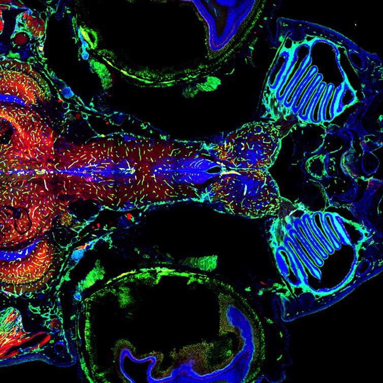
Figure 10. Adult Zebrafish Brain and vasculature, Multi-tile image acquired with Andor Dragonfly 500 and using double camera simultaneous acquisition. Multiple tiles, stitching and in line deconvolution was performed during image acquisition. Image courtesy of Julien Rességuier at NorMIC (University of Oslo).
Acquisition Software
Acquisition software must be able to integrate with the required imaging modalities and applications. It is also advisable to evaluate the basic software package and any extra modules in terms of whether these are required for an application and any cost implications.
Basic software packages for the majority of confocal systems include functionality for time-lapse, Z stack, multipoint, and multichannel experiments, as well as 6D experiments (three channels, time, multimodal acquisition - different channels, time, and Z).
Many more standard or optional tools can be included in the microscope acquisition software package; for example, tile imaging, mosaic imaging, 2D and 3D stitching, real-time stitching, deconvolution, real-time deconvolution and multi-well integration.
The key consideration when selecting acquisition software is that the software is powerful enough to facilitate all required applications.
For further flexibility, it is also worth considering software with scripting capabilities and the capacity for integration with external devices through scripting. This will ensure sufficient flexibility for new applications as research or projects develop or expand.
Analysis Software
Visualization and analysis software is also an important consideration. Ideally, the system should be integrated to allow the acquisition and analysis software to communicate as part of an efficient and productive workflow.
The analysis package should include tools to provide any statistical data needed to analyze and help answer the experimental questions; for example, the capacity to analyze intracellular spots (organelles) and intracellular distances, cell tracking (3D and 2D) capabilities, analysis of neurite branching, spine density, and cell cycles.
A deconvolution option is essential. If this is not included in the acquisition software, it must be integrated into the analysis package. Deconvolution is important because microscopic images are distorted by an optical process inherent to the way photons behave as they pass through the glass. An infinitesimal point will not show itself as a point in an image, but it will exhibit a dispersion characteristic of that optical system.
There are ways to minimize this blur significantly. A very effective way to do so is to use a confocal. Nevertheless, there will always be some convolution, and therefore to have an image that truly represents the object, the raw data should be deconvolved.
A stitcher should be considered as an extra module for the analysis package when working with samples requiring multiple imaging tiles; for example, continuous samples or large organisms. The stitcher must be able to work with big data sets, quickly and effectively joining all the tiles while allowing some overlap between the tiles to deliver a continuous image.
Where there is a need for repetitive analysis, batch analysis capabilities should be considered. This functionality allows analysis to be batch automated once analysis parameters have been defined.
Analysis and rendering software should be able to provide statistical data and present this data in the most appropriate manner by offering multiple rendering and visualization modalities.
Typically, the more modules an analysis software package includes, the more expensive this will be. It should be noted, however, that investment in robust image analysis software can be recovered via reduced analysis time and superior output data quality.
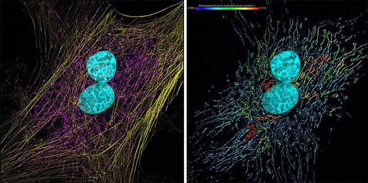
Figure 11. Mammalian cells presenting actin, mitochondria and DNA. Image acquired with Andor Dragonfly 500, an iXon 88 camera and using SRRF-Stream+ imaging modality. Image was processed with Imaris 9.7. The actin filaments (yellow) were segmented with the Surface component. Image by Claudia Florindo, Andor, An Oxford Instruments Company, Belfast, UK
Maintenance Packages
Current confocal microscopes are high-end pieces of equipment offering exceptional quality, but these must still be finetuned to consistently deliver the quality standards set at the time of purchase. Regular maintenance of cutting-edge instrumentation is essential.
A standard warranty is generally included in the purchase agreement when purchasing a microscope, and the buyer can often purchase an extended maintenance package to ensure that the equipment is maintained and calibrated effectively during its first years of use.
Once this initial warranty has expired, most microscope companies will offer three types of maintenance packages: Basic, Medium and Full Coverage.
Basic packages typically feature a pre-defined number of site visits (to diagnose and address issues) and a preventive maintenance visit. Replacement parts are not generally covered, however.
The Medium package typically features the contents of the Basic package and replacement of equipment parts - excluding lasers replacements in most cases.
The Full Coverage package is typically the most expensive, but this package features premium attendance, as well as unlimited callouts to solve issues. This package also offers full maintenance coverage, including all replacement parts, travel expenses, and consulting costs - a comprehensive and priority service provided to the user.
When budgets permit this, a Full Coverage package is the best - 'headache-free' - solution. A maintenance package featuring remote diagnosis and assistance can also speed up the support process.
Most organizations require a balance of cost-effectiveness and service quality, so it is advisable to select a support contract that offers remote diagnosis and assistance, as well as reliable and high quality support.
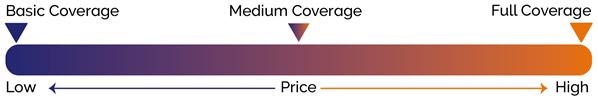
Figure 12. Overall comparison of prices and coverage of maintenance packages. Image Credit: Andor Technology Ltd.

This information has been sourced, reviewed and adapted from materials provided by Andor Technology Ltd.
For more information on this source, please visit Andor Technology Ltd.