This article presents an accelerated test system for power and microelectronic interconnects, which offers rapid product quality screening and reliability assessment. This test system facilitates diverse loading modes to test a range of component geometries and combinations of materials.
Measurement of local velocities by differential laser Doppler vibrometry allows for the calculation of displacements and accelerations affecting a structure under test, and, using this method, fatigue endurance curves up to 109 loading cycles were attained and lifetime was modeled by the Coffin-Manson relationship and compared with existing lifetime measurements of comparable micro-joints found in industrial power cycling tests.
Introduction
Disparities in the thermomechanical properties of materials at interfaces of a contemporary package result in an increase in periodic stresses during standard operation, making these sites critical to the overall integrity of the whole product. Appropriate lifetime analysis for highly miniaturized interconnects poses a considerable challenge.
Additionally, a broad application of 100% quality standards in a range of industries has resulted in a swift growth in reaching standards about reliability in the electronics packaging industry. The introduction of original materials and a notable drop in the time-to-market (reduced to six weeks) has applied considerable pressure on supply chain requirements.
Consequently, quicker and tighter quality assessment of designed components is crucial. Widely used thermal testing practices are a restrictive element in quality assurance of newly developed components. The continued acceleration of thermal/power cycling procedures tends to be purposeless, and as such, the introduction of different techniques seems necessary.
Isothermal mechanical fatigue is under consideration as a very promising alternative for the microelectronic industry. Massive decreases in the duration of tests and energy consumption are believed to be the chief benefits of mechanical testing techniques.
Frequently used thermal/power test techniques employ extreme temperature excursion for the introduction of excessive load level that may result in the activation of failure mechanisms different from the ones seen in-field failures.
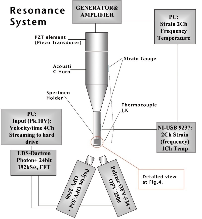
Figure 1. Accelerated ultrasonic fatigue test setup.
The technique developed uses high-frequency resonant vibration as a basis of stress directly at key sites of a modern package (Fig.1). Micro-components put through testing can be forced to vibrate at a wide range of loads related exclusively to an excitation amplitude. Vastly reduced test times allow the use of load levels that are directly comparable with the ones working in existing products, and being unreachable for practical testing times in temperature-based fatigue experiments.
Experimental Setup
The selection of a suitable vibration measurement sensor is restricted by the miniaturization in microelectronics. Small masses, high frequency and acceleration of investigated components necessitate the use of an extremely high precision measuring setup. Inexpensive, high-power ultrasonic bonding equipment working at 20 or 36 kHz is included as a source of excitation. In this case, we employ the use of Telsonic DG-2000 (20 kHz) or DG-100 (36 kHz) ultrasound generators controlled by a personal computer (Fig. 1).
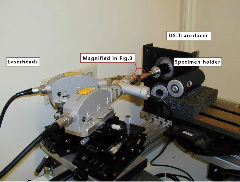
Figure 2. Arrangement at the beginning of the measurement.
To measure the difference of velocity/phase between the specimen holder and the tested component, it’s necessary to carry out a differential measurement using two vibrometers. The Polytec OFV-2500 Vibrometer Controller, with high velocity and frequency levels along with its compact, space-saving form, was nominated and put together with the OFV-534 Compact Laser Head. Positioned on a high-precision translation stage and fitted with a 10X magnification lens, the two OFV-534 laser heads both offer a 3 µm laser spot diameter, which is small enough to agree with the size range of the investigated components (see Fig. 2 and Fig. 3).
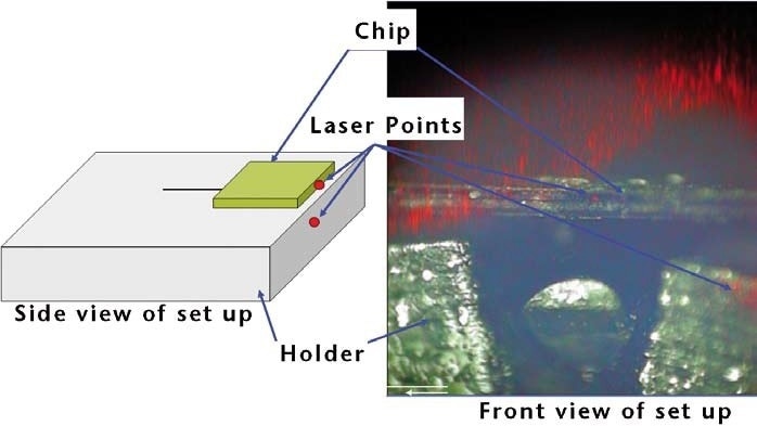
Figure 3. OFV-534 integrated camera view (chip thickness = 70 μm).
The nature of the fatigue measurement means that continuous time signals at relatively high sampling rates with simultaneous frequency analysis and data storage need to be collected. Because of this, numerous data acquisition systems were tested, and the LDS-Dactron Photon+ dynamic signal analyzer completed the system. This DSP-based device facilitates online frequency analysis and simultaneously streaming data to a hard drive at a rate of 192 kilo-samples per second for each of the four channels with 24-bit resolution.
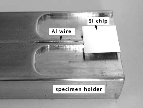
Figure 4. Typical wire-bond specimen prepared for test.
The micro component put into play in this study comprised of single aluminum wire ultrasonically bonded to a metalized silicon chip (Fig. 4).
Results
The velocity/phase difference data we have gathered have been used to reconstruct relative displacement of both vibrating partners, offering obligatory information to compute mechanical stress acting at an interface. Due to the fact that, in standard operation, thermal load stems from a difference in thermal expansion of joined materials, a simple, bimetallic method was employed to establish the Coffin-Manson relationship: cycles to failure Nf versus equivalent temperature excursion ∆T. The data gathered has been compared with results for industrial power cycling tests obtained for the same specimen quality (Fig. 5).
Mechanical and Thermal Life Time Curves
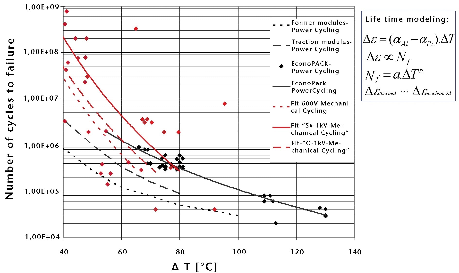
Figure 5. A comparison of power cycling and mechanical cycling results showing good agreement between the two methods of measurement. Power and mechanical results complement well.
Conclusion and Outlook
The suggested enhanced test method was employed effectively for rapid lifetime estimation for a range of microelectronic interconnects, represented by wire bonds. Results compare well with existing power cycling data, but there is a notable shift between the two data sets, which requires clarification.
Additionally, the frequency dependence of results needs to be investigated to rectify the possible influence strain rate may have on the results gathered. As a result of limitations in the equipment, every investigation was carried out at room temperature. This constraint eradicated the influence of thermal processes such as creep and recovery, among others.
An improved system, which facilitates isothermal testing over a temperature range of 125 to 175 °C is currently in the development phase, and our current work is focused on creating a small and semi-automatic testing device that is able to be installed in a microelectronics manufacturing line to offer a rapid quality screening technique for lifetime estimation. Further miniaturization and automation of a fatigue measurement system remain the chief goal of future work.

This information has been sourced, reviewed and adapted from materials provided by Polytec.
For more information on this source, please visit Polytec.