Head gimbal assembly suspensions are approximately a 10 to 14.5 mm length cantilever structure, and their average width is approximately 4 to 6 mm. On the suspension end, there is a roughly 2 to 3 mm square gimbal that holds the hard drive’s read/write head.
These suspensions are manufactured to vibrate at certain frequencies. During manufacturing, modal testing is essential as the hard drive can fail to properly read and write information if the resonance frequencies of the suspension deviate from the design tolerances. This can even result in a head crash.
The testing procedure currently employed involves using a mechanical shaker to vibrate the suspension between 500 Hz and 20 kHz and a laser Doppler vibrometer to determine the consequent motion of the suspension.
There are a number of issues with this testing method. As hard drives become physically smaller, there is an urge to extend the resonance testing of the suspensions to between 20 kHz and 50 kHz, frequencies that are beyond the range of the mechanical shakers used at this time. Additionally, to carry out testing, the suspension must be positioned in a fixture attached to the mechanical shaker. The laser vibrometer senses the resonance frequencies of the suspension as well as detecting the resonance frequencies of the fixture itself.
Lastly, because the suspension has to be connected physically to a mechanical shaker, carrying out in situ tests of a suspension in a hard drive isn’t possible.
The results detailed below show that ultrasound radiation force can be used in order to produce vibration of these suspensions. Similar studies have demonstrated that this technique can be employed for modal analysis of organ-pipe reeds,[1] a MEMS mirror and a MEMS gyroscope,[2] and multiple studies of modal testing of structures in water.[3]
This ultrasound radiation force technique seems to possess a range of unique advantages when compared to using a conventional mechanical shaker as a source of excitation. By using this technique, contact between the suspension and the ultrasound source is eliminated, and as a result there is no distortion of the vibrational modes due to mass loading. In fact, the pairing of ultrasound excitation and laser Doppler vibrometer makes for completely noncontact modal testing.
As demonstrated in section V.A., because the ultrasound can be focused to a small section of the surface of the suspension, this method does not excite vibration of the fixture used to hold the suspension. Sections V.A. and V.B. show that it was possible to selectively excite or suppress different vibrational modes by altering the focus point and phase of the ultrasound excitation.
It was also possible to excite resonances in the suspension from below 500 Hz to at least 50 kHz by utilizing an ultrasound transducer with a wide bandwidth. Finally, Section V.C. shows that it is possible to carry out in situ excitation of the suspension while flying above a rotating disk without needing to attach it to a fixture, making it possible to resonance test the suspension in a fully functioning hard drive as a result.
Theory
Existing papers have extensively detailed the mechanism for ultrasound stimulated audio-range excitation, particularly in water.[4] If the hard drive suspension is ensonified with two ultrasound frequencies, f1 and f2, interference between them generates a radiation force that results in the suspension vibrating at the difference frequency ∆f=f2-f1. A method that has been used to excite small structures is a pair of ultrasound transducers, one of which emits the f1 frequency, and the other emitting the f2 frequency.[1]
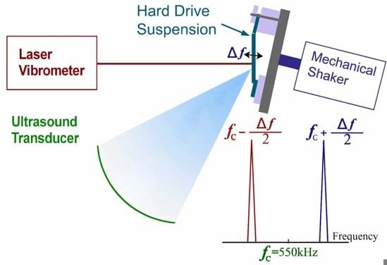
Figure 1. Diagram demonstrating ultrasound radiation force as an excitation method for a hard drive suspension. A modulated signal from the ultrasound transducer, with two frequency components equally spaced around a 550 kHz central frequency, was focused on the suspension. A laser Doppler vibrometer measured the velocity; in order to compare the two methods, it is possible to use a mechanical shaker for excitation instead of ultrasound.
However, in the measurements detailed below, both frequency components were emitted from a single transducer with a double-sideband suppressed-carrier amplitude modulated (AM) waveform [5].
As illustrated in Figure 1, a transducer emitting two different ultrasound frequencies f1=fc-∆f/2 and f2=fc+∆f/2, where f1 and f2 are ultrasound frequencies that are symmetrical about a central frequency fc was able to excite a hard drive suspension. During the experiment, the difference frequency ∆f is swept through a spectrum of frequencies, and the response is measured at each frequency.
If the radiation force at frequency ∆f agrees with one of the suspension’s resonance frequencies, it will bring about a larger amplitude vibration, which will be detected with the laser Doppler vibrometer. The radiation force [6] is produced by variations in the energy density of an acoustic field.
In the following derivation, it’s presumed that the total ultrasound pressure field P(r) at a point r will continue to be the same at frequencies f1 and f2, which are produced by the transducer. However, as the waves of different frequencies cross the distance between the transducer and the arrival point r, they will arrive with different phases φ1(r) and φ2(r). As a result, the total pressure field due to the two frequency components may be written as:
| p(r,t) = P(r) cos[2πf1t + φ1(r)] + P(r) cos[2πf2t + φ2(r)]. |
(1) |
This causes an immediate energy density given by e(r,t)=p(r,t)2/ρc2 ; this energy density will have a time-independent component. This component will be at the difference frequency ∆f, and high-frequency components at multiples of f1 and f2. The radiation force of interest for the current technique is the energy density component at the difference frequency, which can be written as:
| e∆f(r,t) = P(r)2 cos[(2π∆f)t + ∆φ(r)]/ρc2. |
(2) |
Assuming that P(r) is a plane wave, this will give a force in the beam direction on an object of area dS with drag coefficient dr(r) given by: [4]
| F∆f(r,t) = e∆f(r,t) dr(r) dS = P(r)2 cos[(2π∆f)t + ∆φ(r)]/ρc2 dr(r) dS. |
(3) |
The total radiation force as a function of time is the integral of Equation 3 over the entire surface of the object. This radiation force can bring about a vibration of the object at a frequency ∆f. Object vibration because of this radiation force is a function of the size, shape and mechanical impedance of the object.
Experimental Setup
In order to measure the vibration of the suspensions, a Polytec PSV-300 scanning laser vibrometer was used.[7] To ascertain the speed of the vibrating suspension, a vibrometer makes use of the Doppler shift of reflected laser light. By using a scanning laser vibrometer, the laser can be deflected across the surface to measure the motion at numerous points on the suspension surface. This facilitates measurement of the vibrational deflection shapes of the surface.
In order to define these deflection shapes, the software calculates the phase shift between the electrical signal producing the driving force and the vibrational response. A mainly transverse mode will have a constant phase across the whole width of the part, while a torsional mode will have a 180-degree phase shift across the suspension width.
A. Modal Testing for a Simply Supported Suspension.
The apparatus used to gather results in Section V.A. is illustrated schematically in Figure 1. The suspension was clamped at one end with the gimbal resting on the flat surface of a micrometer caliper. The caliper was adjusted so that the downward force induced by the flex of the hinge on the suspension was equal to when this suspension is used in a working hard drive.
The transducer used in this portion of the testing was a custom-made confocal ultrasound transducer for operation in air [MicroAcoustics Instruments, Broadband AirCoupled Transducer sBAT-5]. This transducer generates a focused ultrasound spot with a roughly Gaussian 1 mm diameter beam profile with a 7 cm focal length. This transducer has an inner disk that driven at one frequency, and an outer annulus that can be driven at a different frequency. Each element has broadband performance, with a central maximum positioned near 600 kHz and a bandwidth of over 200 kHz.
For this experiment, the inner disk and outer annulus of the transducer were driven with the same double-sideband suppressed carrier AM waveform. As detailed in Figure 1, to avoid blocking the beam from the scanning vibrometer, the transducer was fixed below the suspension and pointed upwards at approximately 45 degrees. It was also fixed to a 3-d translation stage to allow for the movement of the excitation point on the suspension.
A mechanical shaker was also able to excite the suspension. A Brüel-Kjær 4810 mechanical shaker was put in contact with a clamp that held the suspension support. This shaker produced a very small vibration affecting the whole support system, which were then transmitted to the suspension, resulting in a larger amplitude output from the vibrometer when the driving frequency was equal to one of the resonance frequencies of the suspension.
However, the clamp system possesses its own resonant frequencies. Due to the fact that the shaker vibrated the system in its entirety, the vibrometer spectra would pick up on these resonances.
B. Phase Shifted Diverging (Ex-Focal) Excitation of Suspension:
Along with using the confocal ultrasound transducer, a second method of excitation was employed. This method involved using a pair of diverging ultrasound transducers [Prowave 400WB160] pointed in the direction of the suspension. These transducers possessed a central frequency of 40 kHz and a bandwidth of about 10 kHz, and instead of emitting a focused ultrasound beam, these transducers are diverging with a full beam angle (at 6dB below the maximum) of 45 degrees.
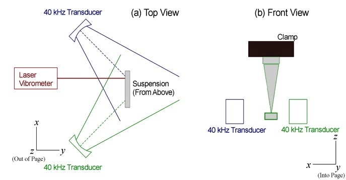
Figure 2. Apparatus used for selective excitation using a pair of 40 kHz diverging ultrasound transducers. The phase angle of the modulated signal between the two transducers was altered to highlight transverse modes when the transducers were driven in phase, and torsional modes when they were driven at a phase angle near 90 degrees.
As seen in Figure 2, a pair of these transducers were positioned approximately 1.5 cm from a suspension that was clamped at one end but left free at the other. These transducers were positioned at a 45 degree angle of incidence, which was relative to the suspension surface.
The modulated waveforms sent to these two transducers were generated using a National Instruments NI6040-E data acquisition board, and there was an adjustable phase difference between the waveforms produced in software for both of the transducers.
As detailed in Section V.B., when the modulation waveform transmitted to the transducers was equal, the radiation force from the two transducers would be in phase. This tends to reinforce vibrational modes that have a transverse displacement, meaning vibrations of the structure that result in a forwards and backwards motion in the direction of the y axis of Figure 2, while suppressing torsional modes, meaning vibrations involving torsion of the suspension around the midline of the suspension, parallel to the z axis of Figure 2, which have a 180-degree phase difference from one side to the other.
Conversely, if the modulation phase between the two transducers varies by around 90 degrees, there will be a 180-degree phase difference between the radiation forces given by the two transducers, which generally reinforces torsional modes as they suppress transverse modes.
V. RESULTS
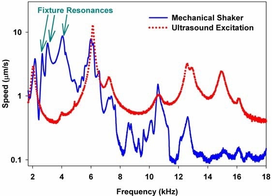
Figure 3. Comparison of velocity spectra obtained using mechanical shaker (solid line) versus ultrasound radiation force (dotted line) as a function of frequency. The mechanical shaker spectrum is far more complex, and includes unwanted resonances in the fixture.
A. Modal Testing for a Simply Supported Suspension.
Figure 3 demonstrates a comparison between the velocity spectra measured by the vibrometer when a mechanical shaker (as seen in Figure 1) was used as an excitation (solid line) and the focused ultrasound transducer (dotted line).
The amplitude of the signal transmitted to the mechanical shaker was changed so that the response curves for the shaker and ultrasound had comparable amplitudes. The mechanical shaker was able to generate velocities over two orders of magnitude larger than those shown here when it was driven at its maximum driving voltage.
Based on the results of these tests, a number of observations can be noted. Firstly, it was demonstrated that excitation through ultrasound generated the same suspension resonances that were generated when the mechanical shaker was in use. Every peak seen in the ultrasound excitation was seen at the same frequency in the spectrum produced using the mechanical shaker.
For every resonances that was observed with both the shaker and the ultrasound excitation, the deflection shapes seen were fundamentally identical. This offers convincing evidence that the ultrasound radiation force is a valid method of measuring the same resonances and vibrational modes that are observable using a conventional mechanical shaker. This result is in line with measurements previously taken that demonstrate the value of using ultrasound as a substitute for a mechanical shaker. [1,2] Further tests showed that this ultrasound transducer was able to excite resonances of the suspension to at least 50 kHz.[8]
Along with the resonances that were observed across both techniques of excitation, the response curve received when using the ultrasound excitation was smoother, and had far fewer peaks than the equivalent response curve for the mechanical shaker. Notably, there were a number of large peaks approximately between 2.5 kHz to 4 kHz. These additional peaks were consistent with fixture resonances caused by vibration of a part of the micrometer, clamps, and support structure responsible for holding the suspension and shaker in position.
The resonances seen in the fixture were observable in all tests using a mechanical shaker, but were not seen in tests during which an ultrasound transducer was used. This was true in tests where the transducer was focused on other parts of the suspension, and tests that did not employ an AM signal to generate the two ultrasound components, but, where they were instead produced by driving the inner disk of the confocal transducer with one frequency f1 and the outer annulus with a different frequency f2=f1+∆f).
In the deflection shapes generated by the scanning vibrometer, these fixture resonances did not seem to possess a well-defined relationship between shape and phase. This absence of a defined structure to the deflection shape is typical of a background vibration, in contrast to the unchanging deflection shapes that are linked to the vibrational modes of the suspension.
In our current experiment, we did not try to ascertain the precise source of these fixture modes. However, in a recent experiment[1] in which resonances were seen in the shaker spectrum that were not present in the ultrasound excitation spectrum, it was possible to separate the particular clamps or supports that led to fixture resonances in some instances.
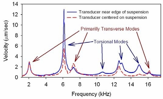
Figure 4. Selective excitation resulting in increased amplitude of torsional modes when transducer was focused near the edge of suspension instead of near the center of the suspension.
Figure 4 illustrates another capability seen exclusively in ultrasound excitation. The dashed curve in Figure 4 demonstrates the response seen when the transducer was focused near the center of the suspension. The solid curve shows the response seen when the transducer was moved approximately 1.5 mm, meaning that the ultrasound focus point was near the edge of the suspension. In an arguably predictable manner, the amplitudes of the resonances that agree with the torsional modes of the suspension were greater when the ultrasound was focused near the edge of the suspension when compared with when it was focused near the center.
It can be concluded, therefore, that by changing the position of the transducer, we were able to change the relative amplitude of different resonances. For the torsional resonance at 6 kHz and transverse resonance at about 7 kHz in particular, it was possible to alter the ratio from approximately 2:1 when the transducer was near the center of the suspension to around 4:1 when the transducer was positioned close to the edge of the suspension.
In a similar fashion, it is important to note that the significant change in the relative amplitude of the two peaks at about 15 and 16 kHz.
B. Phase Shifted Diverging (Ex-Focal) Excitation of Suspension:
A method of selective excitation with an even higher level of versus torsional modes can be achieved by employing a phase-shifted pair of transducers. Using the apparatus demonstrated in Figure 2, the pair of ultrasound transducers were driven with an equal magnitude signal but with a phase angle between the modulation signal (the difference frequency at ∆f) that could be varied.
The solid curve in Figure 5 illustrates the spectrum found when the two transducers were driven in phase. The amplitude of the transverse mode at 2.85 kHz was approximately 3x greater than the amplitude of the first torsional mode at 5.0 kHz. The transverse mode leads as a result of the ultrasound radiation force arriving from transducers to the left and right of the suspension being in phase. This means that there is a principally equal radiation force across the object that is inclined to accentuate transverse modes that have no asymmetry between the two sides of the suspension.
Conversely, the dotted line in Figure 5 illustrates results showing that when the phase difference between the two transducers was on the order of 90 degrees, the resulting 180-degree phase difference in the radiation force between the two transducers tended to excite torsional modes selectively at the same time as suppressing transverse modes.
The amplitude of the torsional mode resonance is over 10x greater than the equivalent transverse mode. Figure 6 illustrates the fairly large changes in amplitude of these two modes that could be found merely by altering the phase angle between the two transducers. This noncontact technique of changing the position and phase gives the unique capability to selectively excite or suppress either torsional or transverse modes. It is important to note that this cannot be achieved using a mechanical shaker.
This unprecedented capability may be particularly valuable in resolving transverse and torsional vibrational modes that nearly overlap in frequency.
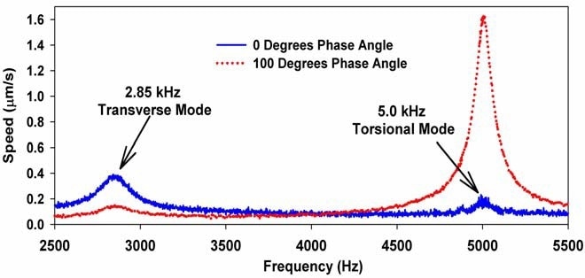
Figure 5. Spectra displaying selective excitation of suspension for phase angles of 0 degrees (showing enhancement of transverse mode and suppression of torsional mode) and 100 degrees (showing enhancement of torsional mode and suppression of transverse mode).

Figure 6. Amplitude of transverse and torsional modes as a function of phase angle between the modulation signals sent to the two transducers of Figure 2. The transverse mode peaks for angles near 0 degrees, and the torsional modes peaks when the angle is near 90 degrees, which corresponds to a 180-degree phase difference between the radiation force produced by the two transducers.
C. In-Situ Excitation of Suspension in a Rotating Disk:
When the tests are carried out as part of the quality control process, the suspension is clamped into a fixture fixed to a mechanical shaker. Since the suspension has to be physically attached to a shaker, this conventional testing protocol makes it impossible to test a suspension that is flying in an operating hard drive.
In direct contrast is the ultrasound excitation technique. Since the ultrasound excitation technique does not need any physical contact between the ultrasound transducer and the suspension, you are able to excite a suspension that is flying in a fully operational hard drive. In order to carry out this test, the beam from the focused ultrasound transducer was focused on a suspension flying over a rotating disk. The vibrometer then measured the vibration.
Figure 7 illustrates the spectra of velocity for a suspension flying above a disk rotating at 4,500 RPM. The solid curve displays the velocity spectrum when the suspension was excited by the ultrasound radiation force. Conversely, the dotted curve illustrates the velocity spectrum when the ultrasound transducer was switched off.
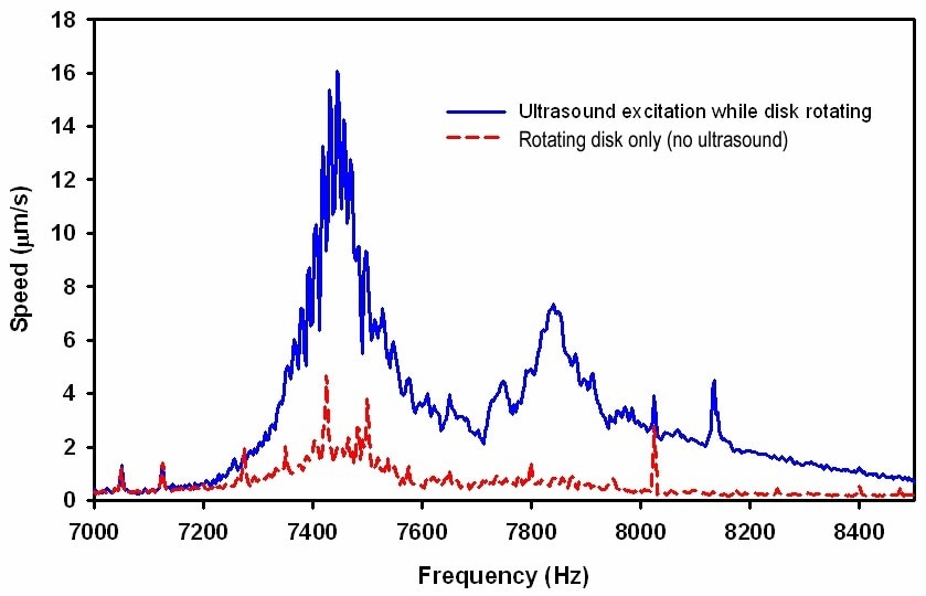
Figure 7. Comparison of velocity spectra observed for a suspension flying above a disk spinning at 4500 RPM with ultrasound excitation on (solid line) and ultrasound excitation off (dashed line). The narrow peaks observed with separation of 75 Hz are harmonics of the 4500 RPM revolution frequency.
This velocity spectrum was produced due to the windage (aerodynamic forces between the flying head and disk, which are both capable of causing vibrations) as well as the excitation brought on by flutter vibrations caused by the surface of the rotating disk. The resonances seen in Figure 7 reveal that it is possible to employ the noncontact ultrasound radiation force to generate suspension excitation over and above the windage when the suspension is not in any special fixture.
If the cover on a hard drive is taken away to expose the suspension to an ultrasound transducer and vibrometer, our tests prove it is possible to carry out modal testing on a fully functional hard drive.
VI. Conclusion
The experiments detailed in this article show that it is possible to carry out noncontact excitation of a hard drive suspension using the ultrasound radiation force. This method reduces the influence of fixture resonances and can generate excitation to at least 50 kHz.
Furthermore, ultrasound excitation has the unique capacity to selectively excite or suppress transverse or torsional modes of the suspension, and can be employed to excite resonances in a fully operational hard drive. Our experiments prove that the ultrasound radiation force is a unique technique that could prove beneficial in the modal testing of hard drive suspensions and similar small structures.

This information has been sourced, reviewed and adapted from materials provided by Polytec.
For more information on this source, please visit Polytec.