In this interview, Matt Scholz, Automotive Business Leader at Radiant Vision Systems, discusses Head-Up Displays, their benefits and where the future of the technology may lie.
What are the benefits of head-up displays?
Head-up displays have three primary benefits and requirements. One is the ability to project information to a driver and improve safety by improving the interaction between the driver and the vehicle on the road.
Another is to ensure that all relevant information is properly presented across various ambient conditions, as cars are driven at all times of the day.
The third is to allow the driver to remain focused on the road while viewing the appropriate information that you would traditionally have to take your eyes off the road to see, whether it be the speedometer or information primarily from the vehicle's center stack.
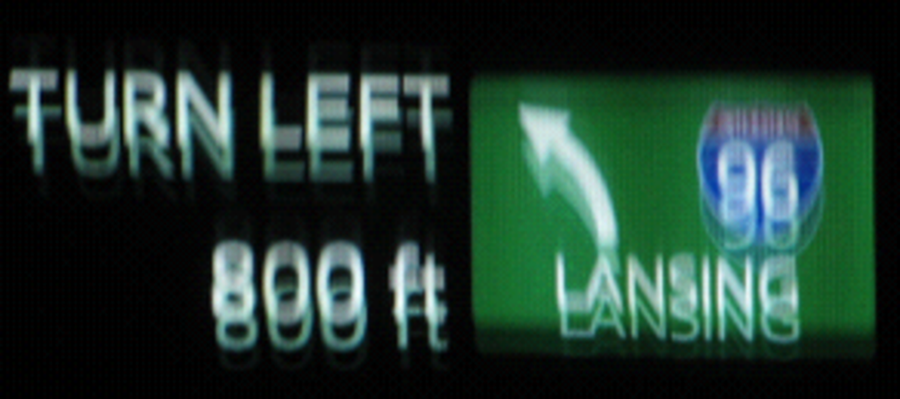
There are a couple of technologies emerging in the future of head-up displays. When looking at the information on the windshield, these technologies could offer different and more seamless visual experiences for the driver. Current conventional head-up displays present information in a 2D fixed orientation at a fixed distance. This is fine when you are viewing only a limited set of information.

HUD with a 2D virtual image at a fixed projection distance
However, we are beginning to add more to the HUD than just a speedometer or map gauge. We are now taking visual elements from the instrument cluster, the center console, and so on, and putting these in the driver's field of view. However, as we put more and more information in the driver's field of view, things start to get cumbersome.
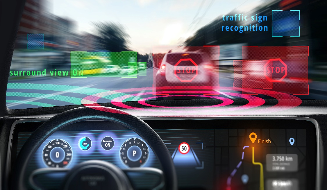
Adding more information to the HUD field of view, without increasing dimensionality or depth of the projection, could create an overwhelming visual experience
The future of head-up displays is in augmented reality. We can add additional depth to the information, we can look at interacting with the objects outside of the vehicle, and we can map information to several different planes, which creates a more intuitive visual experience when providing the driver with information.
What types of head-up displays are there?
When we look at the industry today, we primarily look at two types. From a projection perspective, we have conventional displays, with fixed information on the XYZ plane.
In augmented reality, we have variable information also presented in XYZ space. This information could be presented at 2 meters, similar to a conventional head-up display, but that information could also be projected out to 10 or 20 meters. These projections could encompass and interact with the surrounding environment that the driver sees on the road.
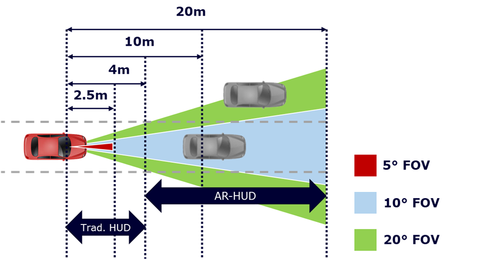
Conventional HUD projection distances versus augmented reality HUD (AR-HUD) projection distances
From there, we break down the dimensionality of the image. We could be looking at a 2D image where the information is flat, or a 3D image that has depth and curvature to it. You can combine these concepts and have a 3D image on a conventional, fixed-projection head-up display, and you can have 2D information presented in augmented reality head-up displays.
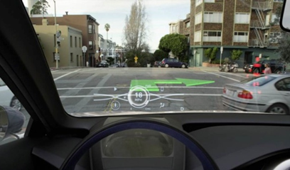
An AR-HUD concept from Toyota that combines variable-distance projections with 3D virtual images: Image Source: Autoevolution.com
What are the benefits of augmented reality over conventional head-up displays?
Looking at the existing technology for conventional head-up displays, there are some problems. Where information is being projected at a fixed distance, the driver is not able to integrate visual information surrounding the vehicle easily with what is perceived in the HUD. This means they are looking at the information, for example, from the speedometer, instead of the external environment while they are driving.
They are also having to change the direction of their gaze or view angle to visually incorporate the rest of the information outside the car. This limits their response time as they are shifting from looking at the head-up display to the environment that they are driving within.
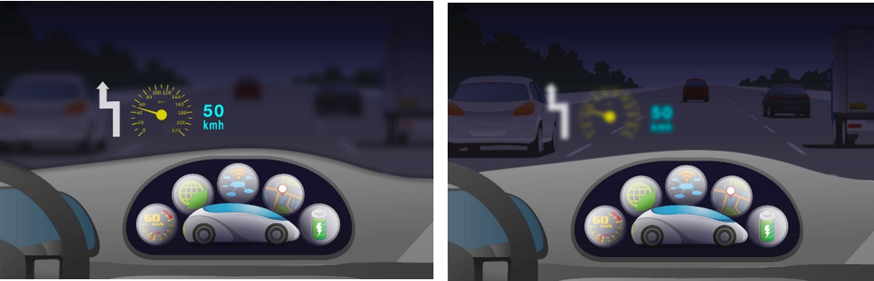
An illustration of the challenge associated with fixed-distance HUD projections, where the driver must shift visual focus from the HUD to the outside environment
Augmented reality aims to overcome some of the limitations that we see in these conventional HUDs. Some people refer to this next phase as HUD 2.0 or other terms, but primarily the terminology that is used in the automotive space today is augmented reality head-up display, or AR-HUD.
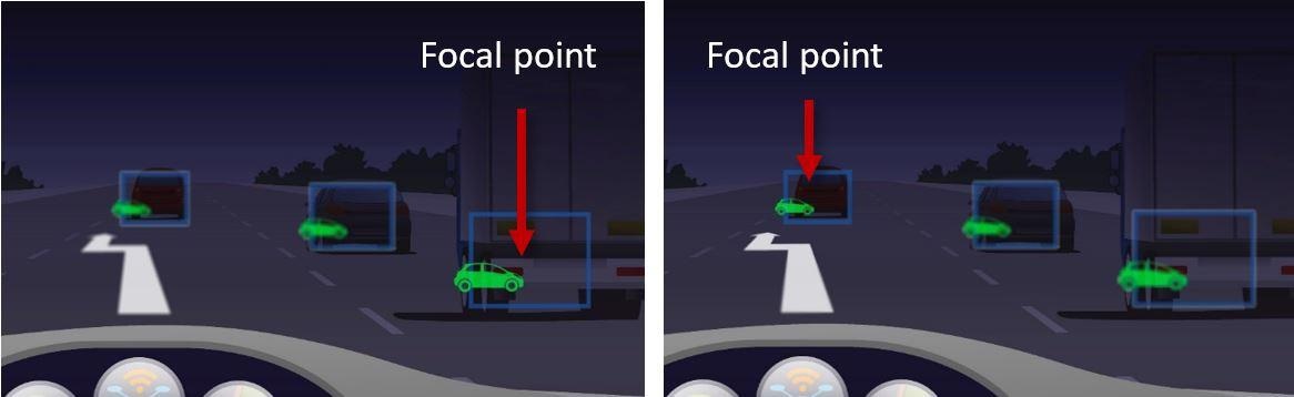
An illustration of the benefits of AR-HUD, where virtual images are projected at distances in relation to external objects, allowing the driver to focus on objects and projections simultaneously
The benefit of this technology is that AR-HUD uses multiple sensors on the interior and exterior of the vehicle to allow the HUD and the driver to integrate the visual experience with the surrounding environment. An AR-HUD can show information like the driver's speed, its lane path and the distance to the upcoming vehicle in relation to elements in the environment. That is, AR-HUD projections can match the depth and positions of external elements so the driver can focus on the HUD projection and the environment at the same time.
What are the projection technologies that enable head-up displays?
The three fundamental technologies currently in production used to project HUD information are laser-based, TFT and DLP technology.
There is a fourth, holographic technology, but a true implementation of holographic content for HUDs has not been widely tested yet.
The combination of technology and projection type manifests head-up display types with unique optical characteristics.
For instance, creating 3D or AR projections using laser-based technology is particularly difficult, given that lasers use a single beam source to produce the image, which performs best when creating 2D fixed augmented solutions for head-up displays. That said, the concept of using lasers for more advanced 3D or augmented reality applications is something that is widely in the pipeline. DLP projector technology or TFT displays are widely used in production today and generally used in conventional and augmented reality head-up displays on both 2D and 3D planes.
Each of the head-up displays has benefits and drawbacks as well as unique measurement challenges to ensure visual performance.
A conventional head-up display projects information at a fixed distance of 2 to 4 meters. Up until now, most of that information tended to be in a 2D orientation without 3D depth. However, we are starting to see the market adapt these new aspects to conventional HUDs.
What are the advantages and limitations of laser-based technologies for head-up displays?
Laser-based technology relies on a laser diode system in a picture generation unit (PGU) with a single-beam projection. The laser beam shoots onto a micromirror plate, which reflects and steers the laser beam to a translucent film attached to the windshield, which then distributes the image out at a fixed distance. Mainly this technology is applied for conventional HUDs, and this distance is 2 to 4 meters.
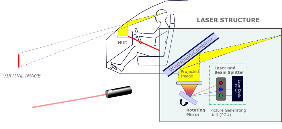
Illustration of an example laser-based HUD system.
There are some significant benefits to laser-based HUDs. They use much smaller components, which saves space in the interior of the vehicle. As they use low energy but have a high output of power, they have extreme luminance capabilities, and so they are capable of a very bright image. Based on the scattering principles of a laser reflecting off a mirror, there is the capability to create an extremely large field of view.
Right now with laser-based technology, automotive manufacturers are interested in windscreen applications, where a much larger field of view over the windshield itself is taken up by the HUD projection versus a conventional HUD, which might project across only five degrees of the driver's field of view.
However, there are also challenges. Because laser technology uses a single beam source to produce images as light is directed toward the windshield, its refraction causes relatively low clarity compared to other HUDs. This can result in fuzzy images, low sharpness, and a reduction in resolution.
Ghosting effects are another problem with this technology. Ghosting is something that all HUDs suffer from, but particularly with laser technology at the moment.
Another challenge that is unique to laser technology is speckle. This is a granular pattern that results when the laser light source is diffusely reflected from the surface. Like a mirror, as the viewing angle changes, visual interference is noticeable, and the speckle pattern changes.
To characterize this, we essentially want to look at the uniformity of the information being presented. We can use an imaging solution to test and look at the luminance uniformity of the speckle distribution, getting a feel for what is visually acceptable for HUDs projecting different resolutions.
What are the advantages and limitations of TFTs?
TFTs are the most basic, most traditional, and the longest-standing technology when it comes to HUDs, and they have been around since the 1980s. The process here is similar to laser, using a PGU to project information out to a mirror.
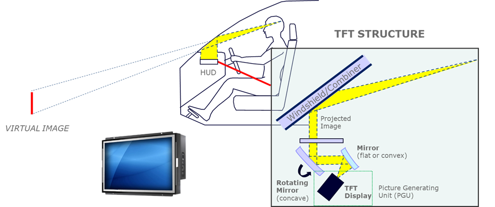
Illustration of an example TFT-based HUD system.
This mirror can be flat or convex in its first diffraction. From there, the projection is reflected onto a rotating concave mirror. From there, similar to the laser, it passes through a set of films and diffusers onto the windshield and is projected out at a fixed distance - or, in other applications that are using augmented reality, at variable distances.
TFTs are the most common HUD technology for several reasons. For one, they are the easiest to implement and the technology is widely available. They are used in all types of HUDs - conventional, 3D, and augmented reality.
TFT display technologies are well understood and there are several regulations regarding their performance and longevity. This is always a challenge to overcome when introducing new technologies in automotive environments. The life cycle is always crucial, and any display in the vehicle needs to be looking at a life cycle from seven to ten years. The benefit of TFT technology is that this kind of longevity is already proven.
The other big benefit of TFTs is reliable color distribution. Since the displays can be easily tuned and calibrated during the production process, you can ensure that accurate, bright, and beautiful information is being presented in the HUD’s projection.
The major limitation that we see with TFT displays is luminance output. Ultimately, the most immediate drawback is creating a bright enough image to deal with various ambient light conditions over which the HUD image is projected.
To exceed or increase the luminance distribution and output from the device, we have to drive a lot of power to the device. The problem with driving an increased amount of power is that we could end up with shifts in color accuracy from the expected distribution.

Example of color shift caused by increasing luminance output of the TFT HUD.
Another limitation is that sometimes, depending on the size of the TFT used or the convention of the distribution from the combiner unit, we can end up with a limited field of view. This is a limitation based on the source display itself, but it is not widespread for every TFT HUD.
What are the advantages and limitations of DLP projector-based technology?
In DLP projector-based technology, an electronics processing unit pushes information to the digital micromirror device (DMD), which projects the image onto a stationary image plane called the diffuser screen. The HUD optics then magnify the image projected onto the windshield where the information is reflected and presented within the driver's eyebox.
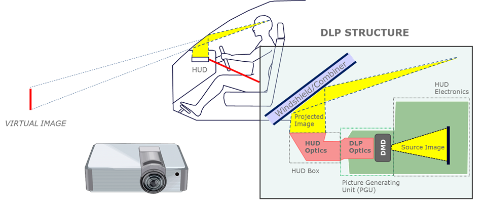
Illustration of an example DLP-based HUD system.
The benefits of DLP are that this technology is easily used for all types of HUDs - augmented reality, 3D, 2D, and anything that we might see coming out in the future. The DLP chips themselves are quite small and extremely powerful, which offers space and cost savings during the implementation into the vehicle.
Thanks to their ability to cast a wide distribution, DLPs can also be used for large-field-of-view HUDs.
The DLP chipsets that we see in the marketplace today are similar to cinema-based projection technology, which means that we have enough experience with them to understand the capabilities for luminance output. We know that they come with the benefit of saturated colors and could potentially offer the best contrast ratio out of the three technologies we’ve discussed.
DLP projection technologies for HUDs rely on a DMD, which is an optical micro-electrical mechanical system that enables spatial light modulation. Each DMD contains up to 8 million individually controlled micromirrors built on top of an associated CMOS memory cell. Improper mapping of the image with the DMD mirror array can cause modulation between contrasting areas of the image. This manifests as spatial frequency, noise, or blurriness that we might see in the projection as the contrasting areas get closer, reducing visible resolution and contrast.
The biggest limitation we see with DLP is the misalignment of the DMD chipset to the array itself and the projection platform. This misalignment leads to abnormalities in terms of clarity and sharpness, drop-offs ghosting, and primary distortion.
Example of HUD ghosting caused by misalignment of elements in the projection and windshield geometry.
DLP projection technology is relatively new to the market. Only a few vehicles currently in manufacturing and production use DLP chips. There is a huge opportunity for this technology going forward, but there are also a lot of challenges that need to be overcome.
What are the requirements for testing and measuring different types of head-up displays?
Applying a measurement or visual inspection system can enable auto manufacturers to employ new HUD technologies while ensuring that appropriate visual quality and performance are being met.
There are fundamental measurement requirements across all HUD technologies. Every single HUD needs to meet tolerances for luminance, chromaticity, uniformity, and contrast, and check for pixel defects or line defects, modulation transfer function (MTF), ghosting distortion, warping, and eyebox limitations.
However, each of the technologies we’ve described might have a slightly different focus or measurement requirement. If we look at AR-HUDs where there is variability and extreme depth of field, things like distortion, ghosting, MTF, and eyebox limitations might play a larger role.
The key differences between HUD measurement scenarios are related to meeting the new demands for the increasing or variable image distance, resolution, and field of view. When we look at conventional HUDs, we see that they have a limited projection depth of up to 4 meters. These images do not change distance or position relative to the exterior environment and are static in regard to the information that is being updated.
On the other hand, augmented reality systems are responsive - they interact with certain elements outside of the vehicle. There is constant change in the information that is being presented and that information is changing over a much larger field of view.
Ensuring sufficient resolution and being able to characterize information at different working distances and in larger depths of field is important on the measurement side.
We can look at measurement requirements for conventional HUDs and AR-HUDs very quickly in a few examples.
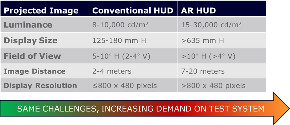
Ensuring the visual performance of HUD systems requires addressing the same basic measurement challenges; however, demands on the measurement system increase as we move from conventional to AR-HUDs.
For a conventional HUD the maximum luminance output is generally about 10,000 candelas per meter squared. However, with an augmented reality system, this is three times as high, with a distance four times larger at maximum. It makes complete sense that you would need to drive a higher luminance output from these devices, and the measurement system should be able to characterize this luminance value.
When we look at the display size or the field of view, we can also see there is a difference in requirements as we shift from a conventional HUD unit to augmented reality. As display size and field of view increase, spatial measurements become more important. In other words, being able to capture images on a complete HUD projection across a broad spatial area is extremely relevant, so field of view and resolution of the measurement system are important.
When image distance becomes variable to match the depths of actual objects - say out to 20 meters in the case of augmented reality - we need an imaging system that has the capabilities and flexibility to adjust its focus based on where information is being presented.
Finally, there is display resolution. The resolution of the HUD that is being projected and the resolution of the measurement system used should be in line.
This means that the measurement platform you are using to characterize the HUD should have a much higher resolution to appropriately identify and characterize the information projected at the farthest distances, which is much farther in an AR-HUD.
What kind of test equipment is needed to evaluate different head-up display projections?
The first problem is that you may require several different pieces of equipment to go through the full characterization process to evaluate the visual performance of a HUD. You need to characterize your HUD from a metrology perspective, looking at factors like luminance and color. You also need to understand the projection distance, the image size of the information distortion, and ghosting that might be apparent within your technology.
Finally, if you do not want to move your test equipment from point-to-point across the projection area - you need a solution that can characterize all of this in a single shot that can analyze the full field of view of the distribution of your HUD.
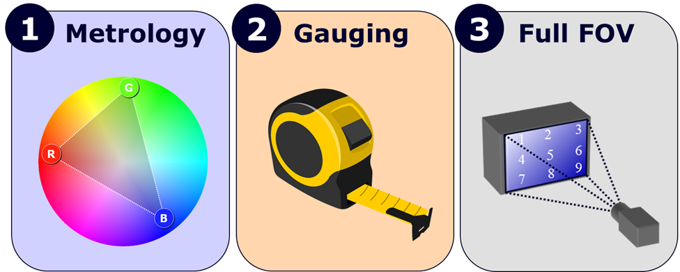
A HUD measurement system must be capable of performing 3 basic tasks: 1) metrology, 2) dimensional gauging, and 3) full-field-of-view analysis.
From a metrology perspective, HUDs require test equipment that can provide you with absolute luminance or chromaticity. This would be any piece of equipment that is photometrically calibrated. Manufacturers could choose a system from a spot-based meter to an imaging photometer or imaging colorimeter.
Using these sensor-based technologies, cooling becomes very important, because it allows you to measure very low light. Measuring something down to 0.0001 candelas per meter squared, as an example, is something that is easy to do with the right sensor, cooling, and general calibration platform.
Instruments with high dynamic range are also important, enabling low light and bright light to be measured within the same scene.
Outside of photometric metrology, you want to understand the dimensions of the information being presented by the HUD and how the projected information is being viewed. The distortion of the image, the warping of the information, or any alignment or abnormalities from a ghosting perspective need to be identified.
Traditionally, human inspection or something like a machine vision camera offer this dimensional inspection capability. In more advanced systems, imaging is applied for machine vision with added photometric measurement benefits.
When it comes to measuring across the HUD’s field of view, we want to characterize everything in context - capturing the full field of view at once to evaluate things like contrast, uniformity, or potential defects such as dead pixels, lines, or blobs. Generally speaking, the choices for measuring across the field of view include an imaging-based platform or a less-efficient spot-based solution such as a spectrometer on a robotic arm. In the latter case, a complete measurement of the HUD field of view requires moving the meter to several different points. This takes a lot of additional time versus an image-based platform.
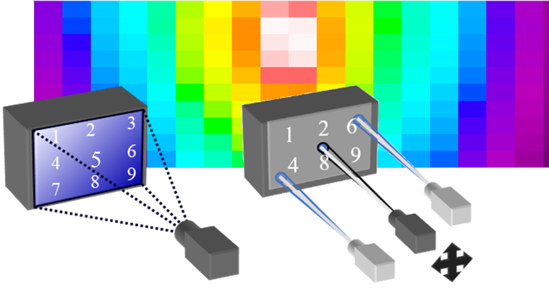
Evaluation across a HUD field of view can be performed point by point using a spot-based meter (right) or at once using an image-based meter (left).
How does Radiant Vision Systems simplify the head-up display measurement process?
An imaging photometer or imaging colorimeter from Radiant Vision Systems allows you to greatly reduce time when it comes to configuring equipment, capturing measurements, setting up your parameters, and properly analyzing your HUD projection.
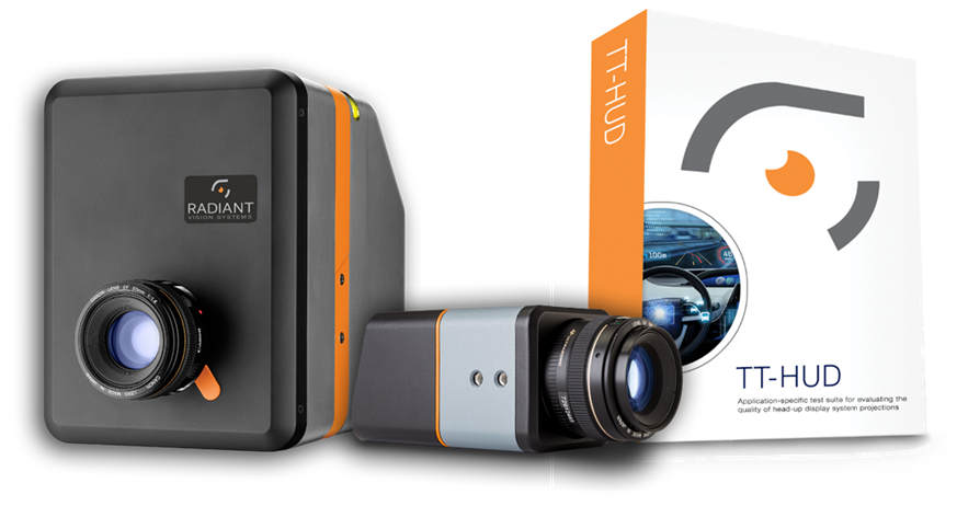
Radiant Vision Systems provides complete hardware/software solutions for fully automated, image-based HUD measurement.
The information and the solutions that Radiant Vision Systems offers combines photometric metrology, dimensional gauging traditionally offered by machine vision systems, and full-field-of-view imaging capabilities.
The primary system for HUD measurement is Radiant’s ProMetric® I-series imaging colorimeter. This is a tristimulus imaging colorimeter, with optical filters matched to CIE color matching functions and standard calibrations, with varying resolutions from 2 to 29 megapixels, in some cases more.
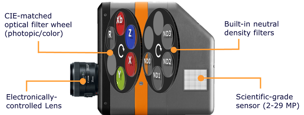
Components of a Radiant Vision Systems ProMetric® I Imaging Colorimeter.
The ProMetric I system has a secondary filter wheel for neutral density filters. This is perfect for HUDs because HUD projections are being driven at extremely large luminance outputs, meaning that saturation of the measurement system’s image sensor is possible. By incorporating neutral density filters into the measurement platform, we can adjust the filters based on the light distribution of the HUD itself to capture the most detail in measurement images.
ProMetric imaging systems all feature electronically controlled lenses, which optimize flexibility when characterizing projections at different working distances and looking at different depths of field in the HUD. From software, we can focus and adjust aperture of the camera to capture a clear image and apply measurement analysis to the information that is being presented. This is facilitated using a system that offers various F-Stops. We can change the F-Stop on the electronic lens. Whether we are looking at F/2.8, F/8, F/11 to F/16 or higher, based on the calibration of the lens, we can adjust the depth of field of our focus based on the characteristics of the HUD projection.
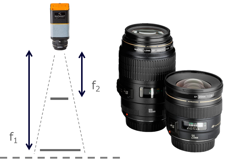
Radiant’s ProMetric® imaging systems feature lenses with electronically controlled focus and aperture settings, calibrated for operation at a range of F-stops.
A big aspect is removing human error from a calculation perspective and reducing any type of manual-based projection or verification information from characterizing distance.
Since the lens is electronically controlled, it can be programmed. This fits very well into an automation platform for characterizing everything from your conventional HUD, to projections out to 20 meters in advanced AR-HUDs.
All of these elements come together as an all-in-one system for characterizing HUDs, and it is the only platform today on the market that offers such a thing.
How important is resolution of a HUD measurement system?
As we focus farther out on the infinite plane, as for AR-HUD projections, achieving clear images at a relatively small scale requires a greater image resolution. Capturing images as far out as 20 meters and evaluating them from a visual perspective can require precise coordinates.
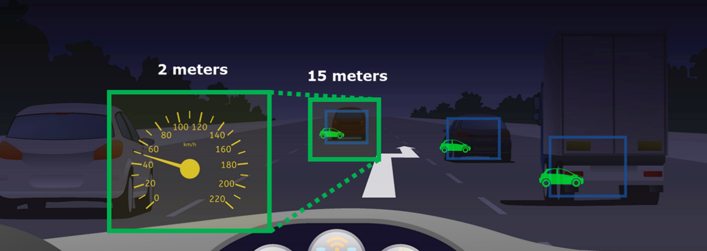
Illustration of HUD virtual images projected at 2 meters and 15 meters. Acquiring sufficient detail at all depths requires sufficient measurement resolution.
If details are missed, this can impact the accuracy of our measurement. An imaging system should match or exceed the resolution of a HUD projection to ensure that the projection itself is evaluated in the exact same detail as it is being produced. This is especially critical for image clarity testing like contrast and MTF measurements.
High-resolution imaging is important for all HUD applications, and at Radiant we typically recommend 16 megapixels and beyond. Using a high-resolution imaging system, we can eliminate any visual anomalies introduced by the limited resolution of the measurement system and isolate on the HUD projection.
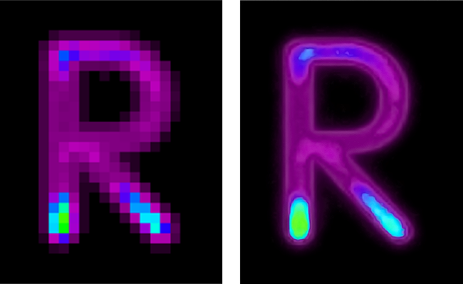
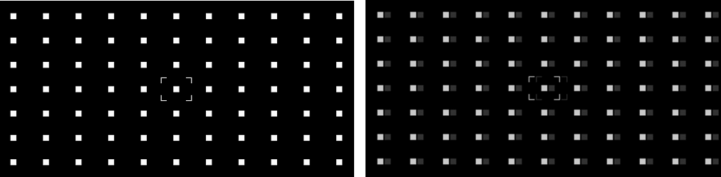
Images captured with a 1MP resolution camera (left) as compared to a 29MP camera (right).
We want to ensure that the information that is being projected by the HUD and being characterized is properly perceived by the measurement device itself. Ensuring that you have twice the resolution or three times the resolution of the HUD’s output is a rule of thumb that we have observed as acceptable when it comes to HUD characterization. Radiant offers imaging system solutions at both 16 and 29 megapixels, and potentially more in the future.
What is the test software provided by Radiant?
Radiant offers a specially developed software called TT-HUD™, which provides a comprehensive test suite for HUD qualification.
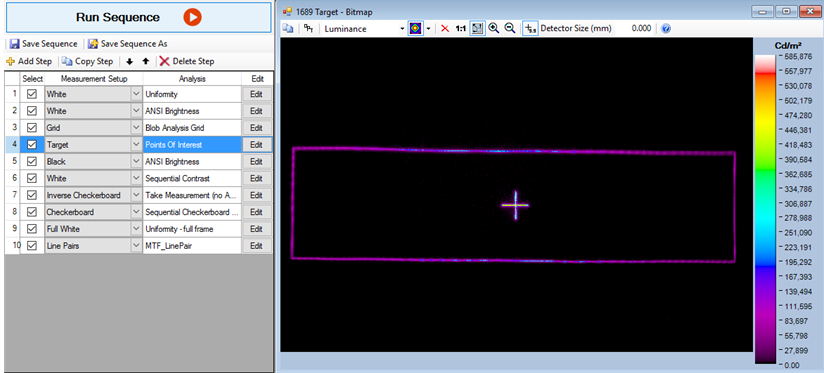
Screen shot from TT-HUD Software performing an eyebox analysis, with various analyses added to a sequence (left) for pass/fail testing of multiple criteria.
This platform enables the characterization of all aspects of existing HUD technology, whether fixed-distance projections or variable, whether we are looking at uniformity, luminance, chromaticity, pixel-level defects, MTF, ghosting, warping, various types of distortion, or contrast.
The whole process is built into a turnkey platform that gives you the flexibility to understand the quality of the visual information projected by your HUD system in terms of customizable parameters, various pass/fail criteria, reports exported in various formats, and open API.
TT-HUD is a test sequencing platform, which means you can load up a queue of different sets of analyses and set different pass/fail parameters for each analysis, running all analyses in rapid sequence in sync with projections on the HUD. Different parameters can be set for ghosting, warping, distortion, and general luminance, uniformity, or color criteria.
We know realize that one tier of the automotive supply chain does not have the same needs as everyone else in the industry. There are advantages and disadvantages to all technologies we see, and they need to be tested quite differently. The TT-HUD platform offers the flexibility to meet needs of different OEMs working across the range of HUD technologies used in the industry today.
How is contrast analyzed by TT-HUD Software?
The purpose of measuring the contrast of your HUD to ensure that you can maintain image visibility when information is superimposed based on the surroundings, as well as being able to distinguish different elements and improve color distinctions of the information being presented.
There are a few different checkerboard methods provided in TT-HUD to measure contrast - diamond, sequential, and inverse checkerboard.
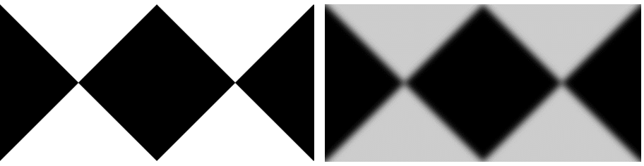
Close up on a diamond checkerboard contrast test image measured with high contrast (left) and low contrast (right).
The Radiant ProMetric and TT-HUD measurement system also offers stray light correction algorithms for contrast and checkerboard measurement applications. This ensures that appropriate information is being characterized and ensures accurate contrast levels across any application.
How is distortion measured using TT-HUD Software?
When we look at distortion, we are looking to evaluate whether the dimensions or locations of projected virtual images are accurate and whether there is any abnormality or missing information in the eyebox or the field of view from the driver's perspective.
TT-HUD can locate and give you information on the centroid or the x,y locations of each virtual element. What the software does is measure deviations from point to point over all vertices across an element, From there, we can create a pass/fail response based on different tolerances of acceptability.
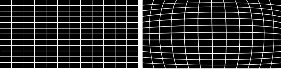
A distortion line grid test image measured without distortion (left) and with barrel distortion (right).
Two primary test platforms for measuring distortion are dot and line grid test patterns.
In a distortion dot grid, we can choose whether we want to look at the information in physical units or whether we want information based on the image sensor positions, such as pixel locations. From a pixel perspective, we can create measurement thresholds and minimum blob tolerance, but where it gets more interesting is the ability to pass/fail the information based on the maximum or minimum column and row spacing.
The same thing can be done in a different way using the distortion line grid. These grids give lots of information, such as the pixel location, and the x,y coordinates of virtual elements in the projection.
How is ghosting measured using TT-HUD Software?
Ghosting is one of the more complex things we test for in HUDs and something that has traditionally demanded human inspection or machine vision. The benefit of TT-HUD is that it is the only photometric measurement solution on the market today that allows you to verify ghosting.
A ghosting analysis test image measured without a ghost projection (left) and with a single ghost projection (right).
The ability to measure multiple ghosts simultaneously is one of the hallmarks of the TT-HUD software. Looking at the output luminance of the ghost and the distance from the true virtual image projection to the primary or secondary ghost is also something the software is able to report out. This gives you all the information that you might need when understanding what your projection limitations might be.
When using the ghosting algorithm, TT-HUD offers users the flexibility to edit the parameters of each analysis. A user can look at the percentage of max luminance of a ghost, characterize the ghost for physical size based on the size of ghosts that they want to detect, or create pass/fail criteria for maximum luminance, minimum displacement, minimum luminance ratio, et cetera.
Why should manufacturers consider Radiant for their head-up display measurement solution?
Manufacturers need a complete solution for characterizing HUDs. whether you care about color or you are only looking at monochromatic information, Radiant offers the hardware coupled with software capabilities to offer a turnkey platform. These solutions can be applied at the R&D phase, quality assurance, or even end-of-line production testing in the vehicle, for consistent and repeatable data across operations.
The Radiant HUD measurement platform was developed in cooperation with manufacturers across the automotive supply chain, and in line with measurement standards set forth by the Society of Automotive Engineers (SAE), to encompass all aspects of HUD visual quality. With imaging system resolutions ranging from 2 to 29 megapixels, calibrated tristimulus color measurement, built-in neutral density filters, electronic lenses, and an extremely versatile software platform, Radiant provides the only turnkey solution on the market for HUD testing - applying one software platform and one piece of hardware to address all measurement criteria.
In summary, regardless of whether we are looking at 2D, 3D or AR-HUDs, we can simplify the measurement process. Whether we are talking about information in a conventional HUD from 2 to 4 meters or out an AR-HUD from 2 to 20 meters, there are no limitations when it comes to characterizing that capability thanks to the benefits of resolution, imaging, and electronic lenses.
As the HUD market is growing significantly year on year, it is an area that Radiant wants to address quickly. We aim to be the leading solution provider for HUD measurement. Providing the best of both hardware and software for automated visual inspection, we have the capability to evaluate against all optical metrology requirements of HUD technologies available today.
About Matt Scholz
With over 10 years of experience working on automotive metrology applications, Matt Scholz has a fundamental understanding of the growing challenges in this industry, including increased performance and quality control for displays, lighting, sensing, and illuminated components. Matt has led projects at all levels of the automotive supply chain, from Tier 1, 2, and 3 vendors to major OEMs worldwide. Matt strives to build on Radiant's success by sharing his expertise on measurement equipment and providing a consultative approach to system integration for automotive applications.


This information has been sourced, reviewed and adapted from materials provided by Konica Minolta Sensing Americas.
For more information on this source, please visit Konica Minolta Sensing Americas.
Disclaimer: The views expressed here are those of the interviewee and do not necessarily represent the views of AZoM.com Limited (T/A) AZoNetwork, the owner and operator of this website. This disclaimer forms part of the Terms and Conditions of use of this website.