Over the past two decades, gain flattening filters (GFFs), used to smooth out (i.e., “flatten”) unequal signal intensities over a specified wavelength range, have evolved significantly.
While the packaging and materials used to fabricate these components have remained almost the same, progress in other areas, including enhanced coating processes and optimized manufacturing uniformity, has driven GFF performance to new heights.
More sophisticated, modern GFFs take advantage of designers’ capabilities to exert more control over peak-to-peak error function (PPEF) - calculated by contrasting the spectral performance of the manufactured filter to a client’s target gain curve specification - and can be encouraged with higher-level performance and given additional functionality.
For instance, applications that require multiple flattening regions or the inclusion of a passband beyond the flattening region.
Gaining just a slight advantage in GFF performance or functionality can have a significant impact on the designers of erbium-doped fiber amplifier (EDFA) modules. While a variation of signal intensity is inevitable, EDFA module designers must limit that intensity difference to meet the demands and specifications of customers.
Suppose the filters (e.g., GFFs) do not incorporate an error function (EF) spec within the customer’s desired range. In that case, the EDFA designer has the challenge of tightening the parameter tolerance control in their packaging to accommodate the signal intensity variation.
For instance, if the module designer’s EF budget for an EDFA is 1 dB, they must first establish how that budget will be spread across components in the unit. If a GFF vendor can offer a filter (or a series of filters) with 0.5 dB EF, the EDFA module designer has 0.5 dB EF to work with across the rest of the system.
But, if the GFF vendor can deliver a filter achieving 0.2 dB EF, the EDFA the designer can now work with an increased 0.8 dB EF budget across the rest of the system. By taking these razor-thin margins into account, Iridian Spectral Technologies has developed a new generation of premium GFFs.
Optimizing GFF Performance and Functionality
Iridian is able to meet the customer’s objectives in a number of different ways, whether offering input on what can be provided before designing an EDFA module or approaching Iridian with exact specification needs once the module has been designed. For instance, in the latter scenario, Iridian has the ability to help correct the customer’s target curve.
Data for the curve, predicated on the customer’s EDFA gain spectrum, is typically measured directly from the erbium fiber.
At times, considerable measurement deviation may be seen on the curve, making it noisy (i.e., erratic and bumpy). Noisy GFF target data can create difficulties when trying to achieve a low PPEF because the modulation depth and steepness of the GFF target can impede how low the PPEF specification can be.
This noisy curve is caused by errors in the measurement process and thus is not really representative of the EDFA’s performance. In theory, erbium fiber performance should be smooth.
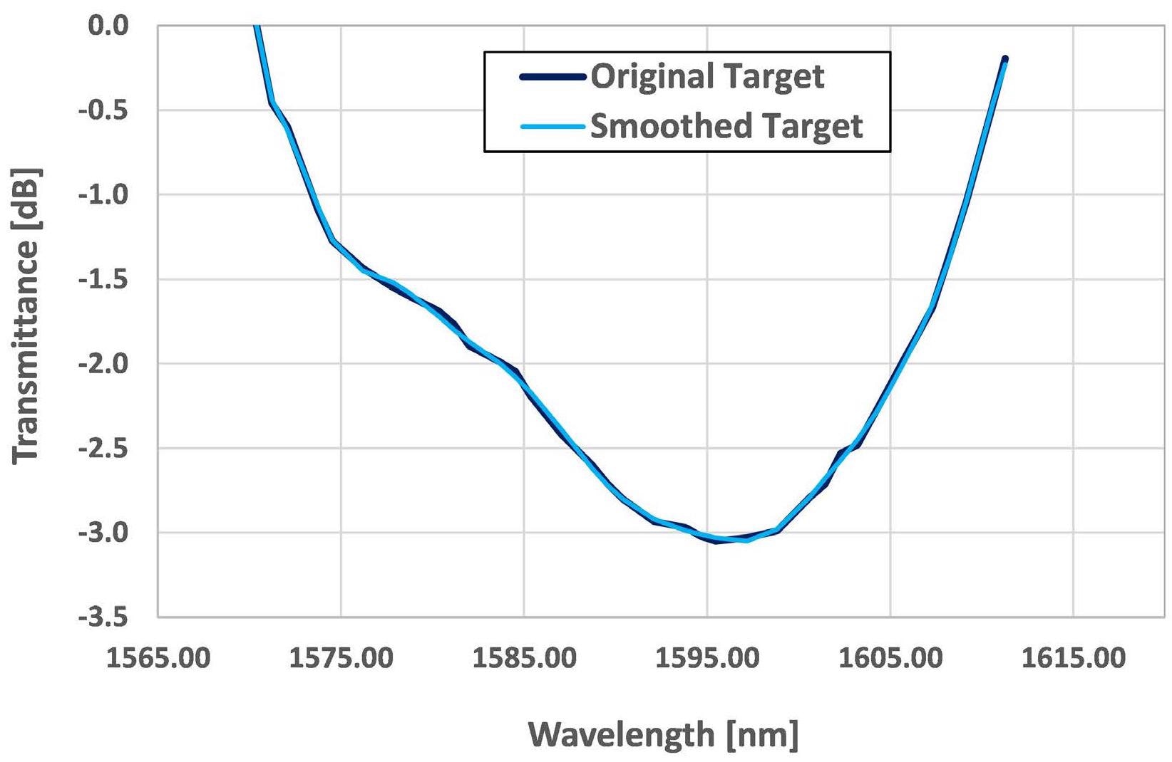
Figure 1. Example of applying smoothed fitting curve in simulation to correct an original target curve measured from EDFA with system noise. Image Credit: Iridian Spectral Technologies
In such cases, before Iridian communicates a GFF design, the experience and technical capabilities of the company facilitate the smoothing of the target curve, bringing it closer to its theoretical optimization and the client’s desired outcome, as seen in Figure 1.
Furthermore, Iridian has the ability to skillfully compensate the EF in GFFs.
By designing and creating a filter set with opposite error functions, the combined PPEF can be reduced. To put it another way, a filter with a precise error function can be created, which has the capacity to compensate for that error function to cancel it out by utilizing a pair of filters, achieving lower overall PPEF across the entire system.
Consider a single GFF filter with a PPEF spec of 0.1 dB. Bringing these filters together should produce a 1-1 PPEF < 0.1 X n dB (with “n” representing the number of filters). For instance, this GFF filter is applied to an EDFA necessitating ten stages of amplification (and, by extension, several stages of error function).
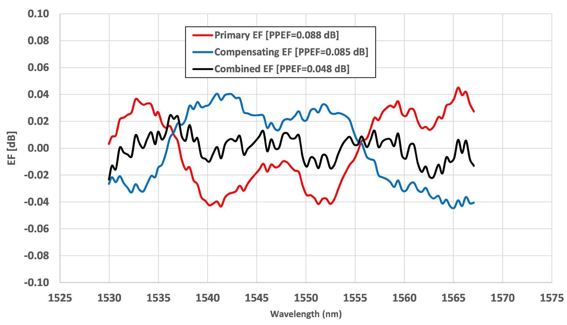
Figure 2. A PPEF compensation example showing the measured EF of a primary GFF (red) and a compensating GFF (blue), as well as their combined performance (black). The example depicted is equivalent to passing through n=2 optical repeaters. Image Credit: Iridian Spectral Technologies
If ten GFF filters with a PPEF spec of 0.1 dB are connected in series to the EDFA, the accumulative EF becomes 1 dB. However, the extra GFFs offset the increasing error function, and the reading should show below 1 dB. Ultimately, this leads to a final EF curve that is less pronounced, as seen in Figure 2.
Iridian also supports customers that seek to generate a passband on the edge of the target curve, preserving high transmission beyond the gain-flattened region for signal carrying or other purposes.
A more conventional GFF curve is smoother on the edges, whereas slightly stretching the GFF wavelength branches on either side or both sides (i.e., the lower wavelength side and the higher wavelength side) suits the customer’s needs.
These sharper curves, sometimes known as “wings,” then become flat in the required spot (Figure 3). These edges are extremely small, often just a few nanometers, which most GFF filter providers find difficult to achieve.
Finally, Iridian customers who need to save space by limiting the number of filters in an EDFA can bring together the functionality of a GFF and a wavelength division multiplexer (WDM) filter by utilizing a hybrid filter (a subset of Iridian’s premium filters).
In a hybrid GFF design, Iridian has the capacity to optimize the transit band limitation between the GFF curve band and blocking bands out of the GFF range (discover more about hybrid GFFs and their capabilities here).
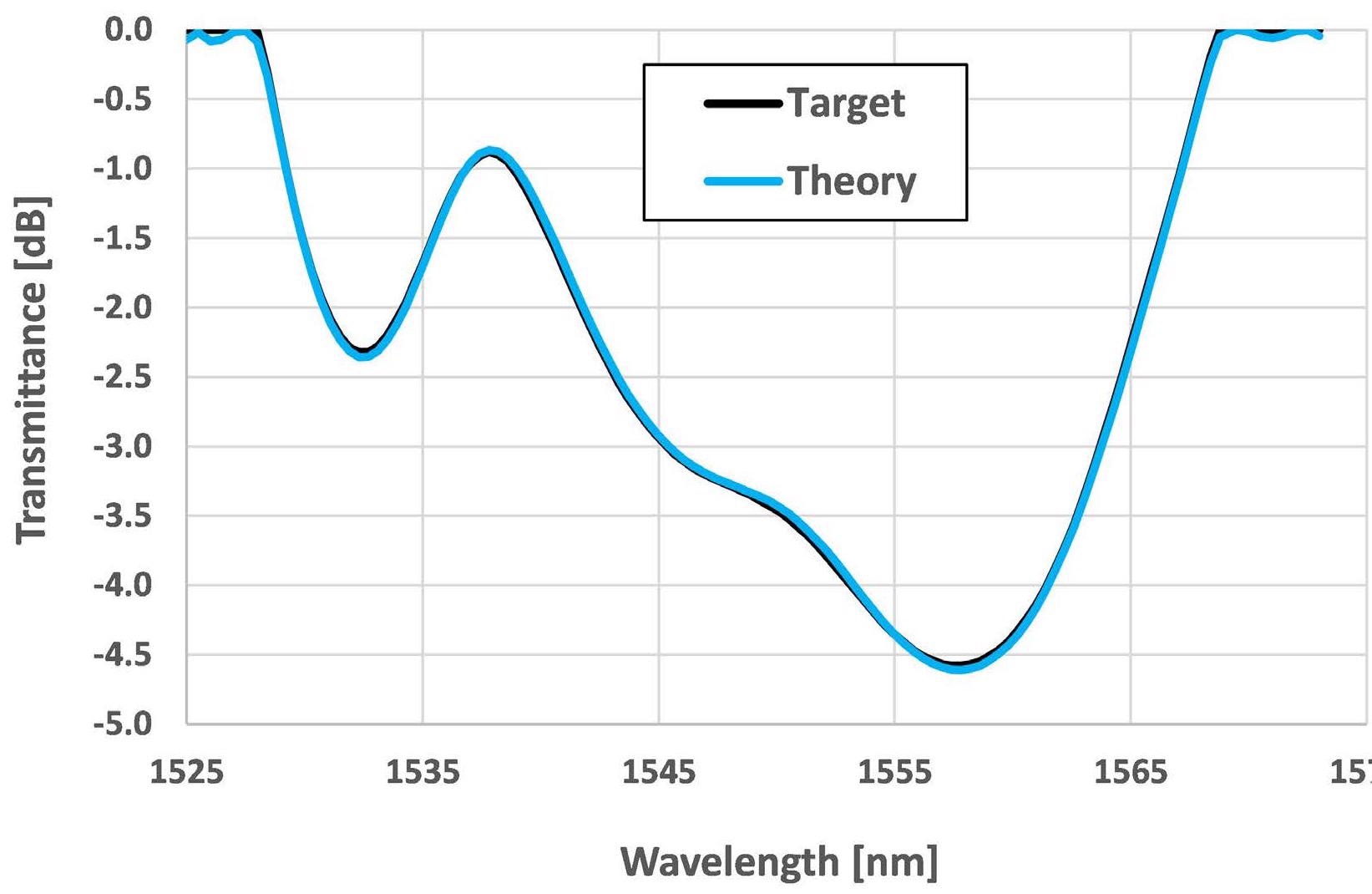
Figure 3. A GFF target curve with “wings.” Adding extended wings on both GFF curve sides optimizes the performance of “edge channels” operating within that wavelength range in the EDFA module. Image Credit: Iridian Spectral Technologies
Final Thoughts
EDFA applications may vary significantly greatly, but concerns about weight, size and power, as well as cost (SWaP-C), tend to dominate module design. Iridian possesses the experience and expertise necessary to help its customers satisfy even the most stringent SWaP-C demands by offering premium GFFs with high PPEF performance that facilitate overall simplicity in the design of a module.
Whether wanting to directly tackle combined EF - constructing an EDFA, calculating its EF, and then implementing GFFs - or collaborating with Iridian to build an EDFA using its filters implemented into the design up-front, Iridian can help.
Iridian is persistently looking to enhance its design and manufacturing processes to further reduce costs for customers, as well as preserve high throughput yields even at a tight EF. Moreover, Iridian exercises precise control from coating run to coating run to ensure that the high-quality result is repeatable.
For further information, contact Iridian and explore the additional resources links below.
Additional Resources

This information has been sourced, reviewed and adapted from materials provided by Iridian Spectral Technologies.
For more information on this source, please visit Iridian Spectral Technologies.