Transmitted Light Microscopy
In transmitted light microscopy, the light passes through the sample. This is where the term “Transmitted Light Microscopy” came from.
Brightfield is the most straightforward technique. Brightfield is used to take images of thicker tissues or tissues stained with histological dyes, such as haematoxylin and eosin stains, to provide contrast and detail.
However, when it comes to taking images of samples that are thinner and unstained, brightfield is not the best choice as the structures inside the cells do not generate enough contrast to be viewed easily by the human eye. As a result, other techniques of transmitted light microscopy techniques have evolved, and these are set out below.
Phase-contrast microscopy uses phase plate rings in the optical path that generate higher phase differences between the structures within the samples and translate into a higher contrast image.
This method greatly improves on transmitted light microscopy, as it allows the structure of thin unstained samples to be observed. However, the problem with this technique is the resultant bright halo - the “phase halo” - that can hide detail.
Differential Interference Contrast (DIC) delivers high contrast and high resolution images. It has complex and expensive optics, which rely on the use of two polarizers. The first is placed before the light hits the sample, and the second is placed after the light is emitted.
The polarized light rays will combine with a minor shift, which produces high contrast and resolution images.
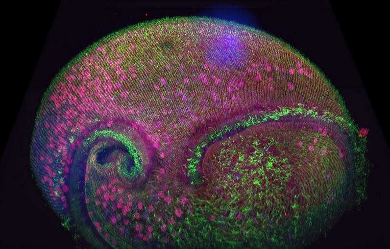
Figure 1. Confocal volume of Stentor pyriformis imaged with Andor Dragonfly. 253 optical slices, captured with 40x (1.1 NA) water objective with 40 µm pinhole on Dragonfly. Courtesy of Victoria Yan, TU Dresden. Special thanks to Drs. Wallace Marshall and Vincent Boudreau and the Physiology course at MBL, Woods Hole.
Differential Phase Contrast (DPC) is a recent development in transmitted light microscopy (Figure1). Andor has developed DPC further and implemented it in the new benchtop confocal microscope BC43.
DPC uses the principle that the phase gradient can be extracted from a pair of intensity images taken with opposite illumination angles. It is possible to have a quantitative phase reconstruction method for differential phase-contrast images using a mathematical algorithm for DPC images (Tian L. & Waller L., 2015).
DPC does not need specific objectives (like phase contrast objectives), polarisation optics (as in DIC) and it can be used to image birefringent specimens (Tian L. et al., 2014).
DPC also allows constant access to the sample in all areas, not dependent on tweaking angles or adjusting polarisers. In contrast to DIC, the DPC images can be attained via plastic dishes. This is practical and often essential for many biological imaging applications.
DPC is able to deliver high contrast and high-resolution imaging even in unstained thin samples (Movie 1).
In conclusion, DPC is an inexpensive, easy-to-use transmitted light microscopy technique that accomplishes large illumination angles and avoids the difficulties of mechanical scanning.
DPC combines the best of both phase contrast and DIC imaging techniques. Therefore, DPC is an outstanding “label-free” imaging method with clear applications in live sample imaging.
Both Andor’s Dragonfly and BC43 microscope systems have transmitted light technologies available. DPC has also been seamlessly integrated into the novel benchtop confocal imager BC43.
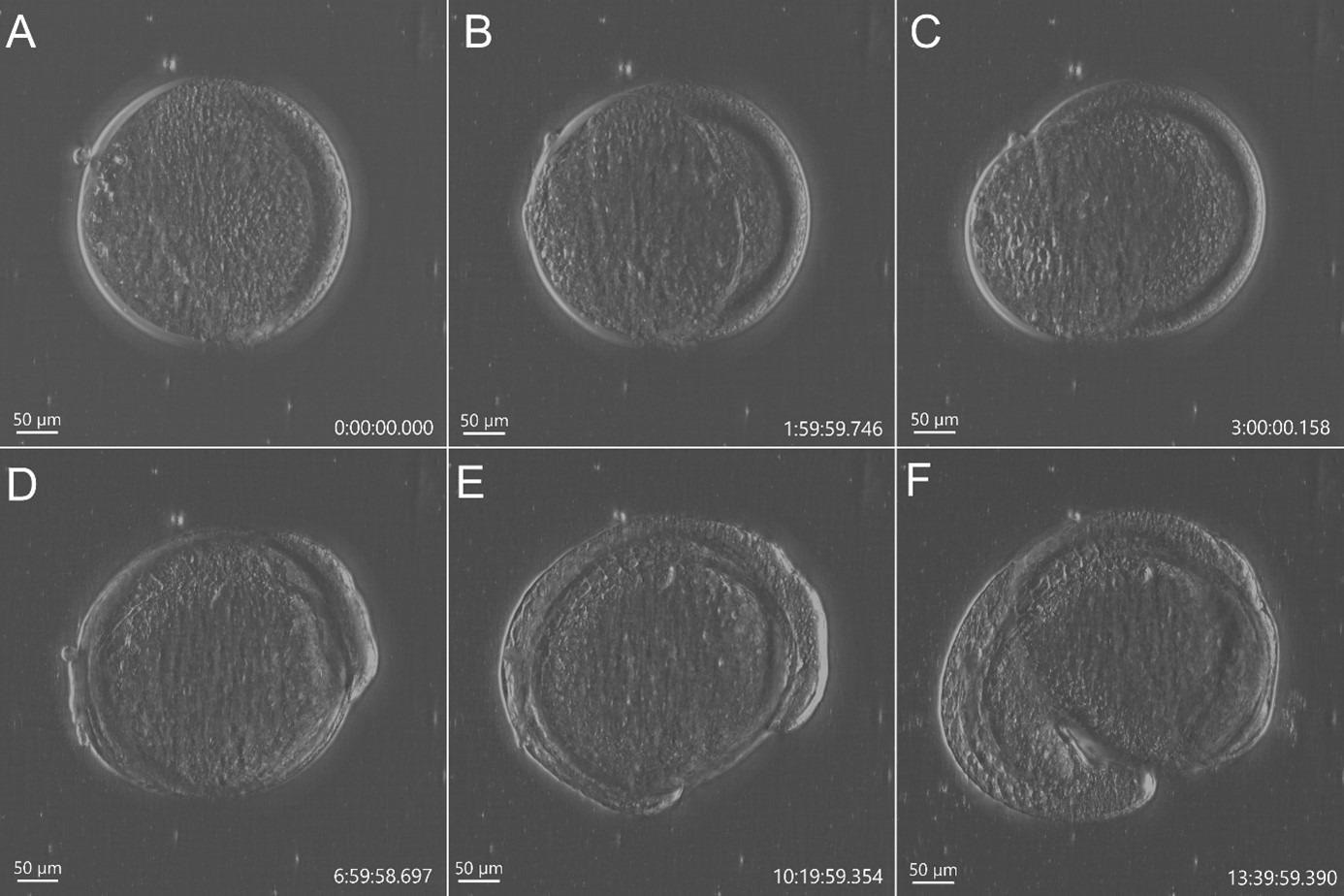
Figure 2. Stain free imaging of Zebrafish development using DPC imaging modality from BC43. Single field image of live Zebrafish embryo image with BC43 using the 10x imaging objective (1,84 mm of field of view). Live embryo imaged from dome stage (A) until 17 hours post fertilization (F). Embryo at 50% (B) and 75% (C) epiboly, 3- (D) (E) somite stage. Zebrafish embryo was imaged with a 10X objective. Image is a maximum intensity projection of 35 stack, covering a full range of 700 µm, and captured every 20 min for 14 hours. Embryo was incubated at 28 ºC. Image by Marco Campinho, Universidade do Algarve and Claudia Florindo, Andor Technology
Widefield Fluorescence Microscopy
The full illumination of the sample and the subsequent detection of all emitted light from the sample characterizes Widefield imaging. This method will capture both the ins and outs of focus light.
Widefield fluorescence microscopy is an optical method that captures all the light from the sample (in and out of focus). The basis of this method is the physical phenomenon of fluorescence.
Fluorescence is instantaneous and ceases to exist as soon as the excitation light is turned off. Widefield fluorescence illumination can be achieved using mercury and xenon bulb LED light sources and laser-based widefield illumination.
The phenomenon of fluorescence can be described in the following steps:
- A molecule (or molecular system) absorbs light of a specific wavelength; i.e., the excitation wavelength.
- The excited electron will “jump” to a higher energy level in the atomic orbitals.
- The excited electron will move back to the ground energy state and emit a photon.
- The emitted photon will have a longer wavelength (less energy) than the exciting photon, i.e., the emission wavelength.
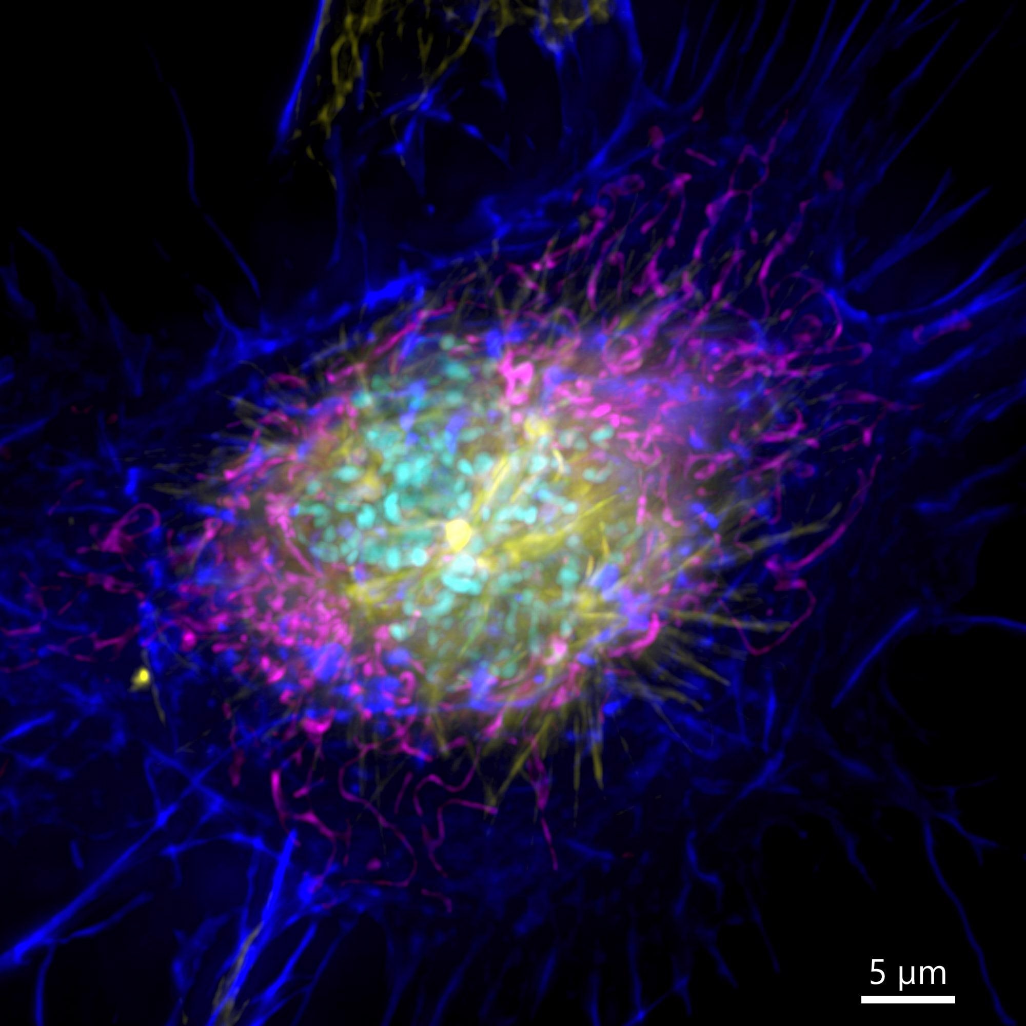
Figure 3. Image of a mammalian cell acquired using widefield modality, using Andor BC43. Image shows the widefield image of a prophase cell ll. Image was further deconvolved after acquisition and is a Maximum intensity projection of 35 Stacks over a 7 µm range. Dark blue-actin, magenta-mitochondria, yellow-microtubules, Cyan-DNA. Image by Claudia Florindo – Andor Technology.
Mercury-Arc lamps were the first light sources used in widefield fluorescence microscopy. One benefit of mercury bulbs is that the excitation wavelengths have numerous peaks that coincide with the excitation wavelengths of many of the fluorophores typically used in microscopy (313, 334, 365, 405, 436, 546 and 579 nm).
However, the illumination is not uniform across the whole spectrum, making it hard to quantitatively analyze samples. Additionally, infrared and near infrared fluorochromes are not excited by this light source, and mercury is a hazardous material that should be avoided if possible.
The Xenon-arc lamps have a much more uniform illumination across the visible spectrum than Mercury-Arc lamps. However, this is of lower intensity and has lower illumination power in the near UV/ UV range.
As the emission is weak, using common DNA staining dyes, such as DAPI and Hoechst, is rather challenging. In addition, these lamps have a limited life span that is decreased if the illumination is switched on and off frequently.
LED light sources have evolved into highly efficient light sources with a long life span, which are not affected by the system being switched on and off. These light sources have become popular and have replaced some of the once common Mercury and Xenon light sources.
Andor has incorporated laser-based widefield imaging into its confocal systems. It delivers sharp and precise illumination excitation, which consequently allows excitation of the sample fluorophores.
Laser widefield imaging can deliver both controlled very low illumination intensities needed to image a highly sensitive sample and the much higher laser powers required for higher-end technological applications, such as dSTORM super-resolution microscopy.
Widefield microscopes also have bandpass filters that selectively permit the wavelengths of the desired emission to pass through to the detectors. The detectors are cameras - generally EMCCDs or sCMOS.
In summary, widefield systems capture all the light emitted from the sample and do not provide optical sectioning.
For this reason, they are not suitable for thick and highly scattered samples. However, as they capture all the light that is emitted from the sample, they are useful for highly photosensitive samples, fast events, thin samples and live-cell imaging.
Samples that are suited for widefield imaging are thin low scattering samples, including yeast, microalgae, bacteria and monolayer cells. See Movie 2 and Figure 3 for examples of widefield imaging. Andor confocal systems solutions Dragonfly and BC43 deliver laser-based widefield imaging, details of which are set out below.
Andor Dragonfly offers all the technological options in widefield imaging. From standard routine applications to simultaneous dual color imaging and even high-end options that necessitate high laser powers such as dSTORM super-resolution.
Andor BC43 is the workhorse for routine research and applications which require less specialized microscopy techniques, although this does not result in a modest option.
With BC43 the user can acquire up to 4 different fluorescent imaging channels, and therefore the same number of different structures can be fluorescently labeled and sensed with BC43.
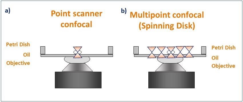
Figure 4. Schematic diagram illustrating the pattern of illumination for point scanner and spinning disk microscopy. Point scanner confocal microscopy (a) focuses a single point of laser light through a small aperture (pinhole) and scans sequentially across the sample point by point. Spinning disk confocal microscopy (b) illuminates the sample with a rotating pattern of 1,000's of pinholes for complete simultaneous confocal illumination. Image Credit: Andor Technology Ltd.
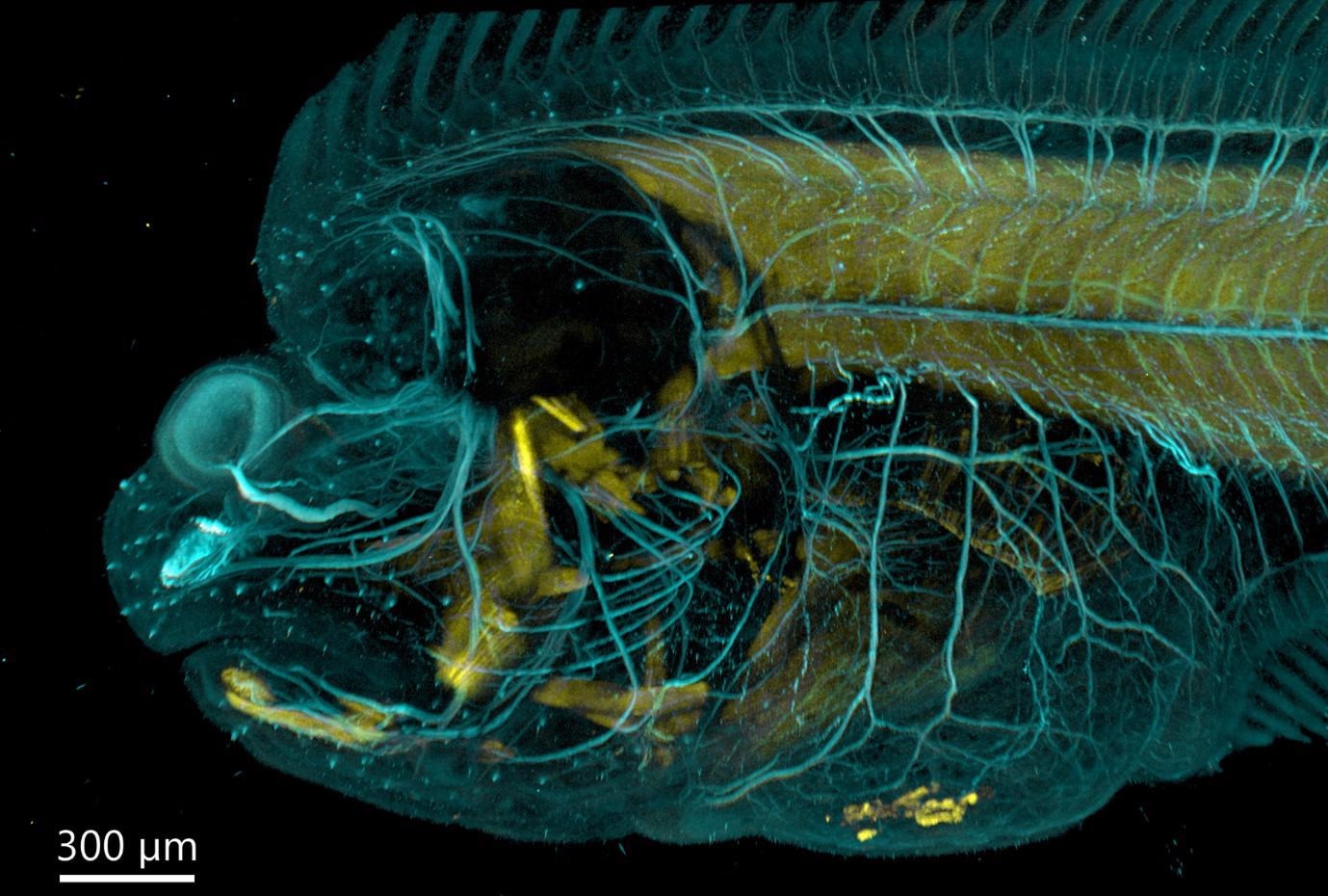
Figure 5. Flat fish imaged with BC43 using confocal option. Image was acquired with Andor Bench Top Confocal – BC 43 using multiple tile acquisition and montage. 6 tiles were acquired to compose the image covering a range of 554 µm. Image rendered with Imaris (Image credits Marco Campinho, Universidade do Algarve and Claudia Florindo, Andor Techonolgy).
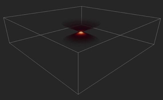
Figure 6. Image of a PSF in 3D. Image shows the distortion of a single point imaged in an optical system, the Point Spread Function (PSF). Image Credit: Andor Technology Ltd.
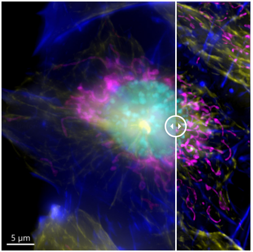
Figure 7. Image of a mammalian cell acquired using widefield modality, using Andor BC43. Image shows the widefield image, before Deconfolution (left), and after deconvolution (right). Image is a maximum intensity projection of 35 Stacks over a 7 um range. Dark blue-actin, magenta-mitochondria, yellow-microtubules, Cyan-DNA. Image by Claudia Florindo - Andor Technology
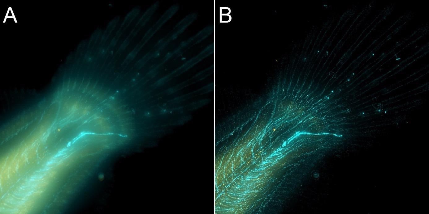
Figure 8. Flat fish image in widefield mode using BC43 and deconvolved with Clear-View GPU based deconvolution. Flat fish tail, acquired with A) widefield imaging modality and B) deconvolved. Widefield imaging modality is not the best option to image thicker samples – although the image benefited from restoration with Clear-View GPU based deconvolution, the original fish was too thick to be imaged in widefield modality. The result can be greatly improved if the original image is acquired using the confocal option. – see figure 9. Image by Marco Campinho, Universidade do Algarve and Claudia Florindo Andor Technology.
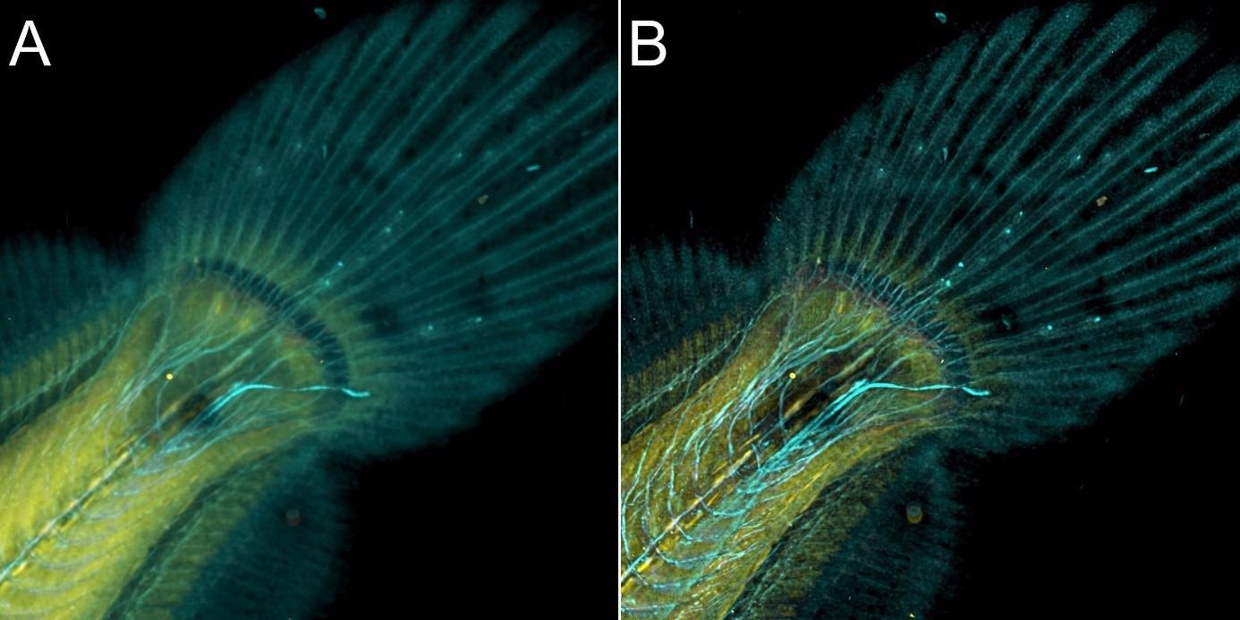
Figure 9. Flat fish image in confocal mode using BC43 and deconvolved with Clear-View GPU based deconvolution. Flat fish tail, acquired with A) confocal imaging modality and B) deconvolved. Confocal imaging modality is the best option to image thicker samples, the quality of the image was further improved with deconvolution with Clear-View GPU based deconvolution. Image by Marco Campinho, Universidade do Algarve and Claudia Florindo, Andor Technology.
Overview on Andor Microscopy Systems Solutions
Andor offers excellent confocal imaging systems adapted to the needs and applications of different users. Andor’s multipoint confocal microscopes are developed to ensure that users will benefit from:
- Patented uniform illumination (Borealis)
- Highly sensitive detection (sCMOS and EMCCD Andor detectors)
- Ultra-fast confocal imaging (confocal speeds up to 400 fps)
- High background rejection (image thick specimens from 100’s of nm to the mm range)
Andor provides two confocal imaging systems, the BC43 and Dragonfly.
The BC43 is a high-quality confocal system. It is an all-in-one, simple, compact and highly user-friendly instrument. BC43 is an imaging technology that is ideal for multiple life sciences applications. It can even fit in the corner of a core facility or on a laboratory bench.
On the other hand, the Dragonfly is a high-end confocal system. Dragonfly is a complete imaging system appropriate for most life science applications; from more routine applications to high-end ultra-fast imaging.
Two tables are presented below that may help users select the confocal that best suits their imaging needs
1- Microscope selection by application
2- Microscope selection by imaging technique
Please note that the tables suggest which applications are most appropriate to different products. However, everyone’s experimental requirements vary. Users can talk to an expert at Andor about their specific requirements.
Microscope Selection by Application
Table 1. Source: Andor Technology Ltd.
Application
Area |
Type of
Experiment |
BC43 |
Dragonfly 200 |
Dragonfly 500 |
| Cell Biology |
Intracellular structure |
 |
|
|
| Cell cycle - cell division |
|
|
|
| Microtubule dynamics |
 |
|
|
| Mitochondria imaging (fixed) |
|
|
|
| Mitochondria imaging (live) |
|
|
|
| Membrane dynamics (eg: cytokinesis) |
|
|
|
| Intracellular trafficking |
|
|
|
| Cilia imaging (>50 fps) |
nil |
|
|
| Vesicle trafficking |
nil |
|
|
| Chromatin remodelling |
nil |
|
|
| Developmental Biology |
Early embryo development |
|
|
|
| Limb formation |
|
|
|
| Tissue sample preparations |
|
|
|
| Paraffin sections |
|
|
|
| Whole organisms up to 500 µm thick |
|
|
|
| Whole organisms 500 + µm thick (depends on sample transparancy) |
|
|
|
| Fertilization |
nil |
|
|
| Pathogen-host interactions (virus, bacteria, fungus) |
nil |
|
|
| Intracellular trafficking |
|
|
|
| Vesicle trafficking |
nil |
|
|
| Organoids up to 500 µm + thick |
|
|
|
| Organoids up to 500 µm + thick (depends on sample transparency) |
|
|
|
| Blood flow studies |
nil |
|
|
| Cancer Biology |
Large tissue slices |
|
|
|
| Live imaging cell movement & division |
|
|
|
| In-vitro cell invasion |
|
|
|
| Organoids up to 500 µm thick |
|
|
|
| Organoids up to 500 µm + thick (depends on sample transparency) |
|
|
|
| Immunology & Diseases |
Fixed tissues |
|
|
|
| Large samples up to 500 µm thick |
|
|
|
| Large samples 500 µm thick (depends on sample transparency) |
|
|
|
| High speed live imaging |
|
|
|
| Blood flow |
nil |
|
|
| Microbiology |
Intracellular structure (Super-Resolution SRRF-Stream) |
nil |
|
|
| Intracellular Structure - Molecular interactions (Super - Resolution dSTORM) |
nil |
nil |
|
| Cell surface infection dynamics - TIRF |
nil |
nil |
|
| Neurosciences |
Tissue culture (live and fixed) |
|
|
|
| Tissue sectioning (live and fixed) |
|
|
|
| Whole brain imaging (up to 500 µm thick) |
|
|
|
| Whole brain imaging 500 µm + thick (depends on sample transparency) |
|
|
|
| Calcium imaging (waves up to 40 fps) |
|
|
|
| Calcium imaging (puffs, sparks >40 fps) |
nil |
|
|
| Live vesicular transport |
nil |
|
|
| Single molecule live imaging |
nil |
|
|
| Growth cone |
nil |
|
|
| Receptor localization & recycling |
nil |
|
|
| Biophysics |
Protein-Protein Interactions |
nil |
|
|
| Protein membrane dynamics |
nil |
|
|
| Single protein transport |
nil |
|
|
| Endo and Exocytosis |
nil |
|
|
| Localization-based Super Resolution |
nil |
|
|
| Expansion Microscopy 1,2 |
|
|
|
| Multiplex Imaging - Spatially resolved transcriptomics 2,3 |
nil |
|
|
| Multiplex imaging - Spatially resolved proteomics 2,3 |
|
|
|
Key: Nil - Not Suitable
- Partially Suitable
- Recommended
Notes:
1. Depends on laser power to image through the depth of the sample.
2. Depends on throughput requirement. BC43 has just one camera and does not capture as fast as Dragonfly.
3. BC 43 is limited to 4 laser lines. Spatial transcriptomics typically requires 5 lines.
Microscope Selection by Imaging Technique
Table 2. Source: Andor Technology Ltd.
| Technique |
Technology |
BC43 |
Dragonfly 200 |
Dragonfly 500 |
| Transmitted Light Microscopy |
Differential Phase Contrast (DPC) |
✘ |
✘ |
✘ |
| Phase Contrast |
✘ |
✓ |
✓ |
| Differential Interference Contrast (DIC) |
✘ |
✓ |
✓ |
| Widefield Imaging |
Up to 4 Channels |
✓ |
✓ |
✓ |
| More Than 4 Channels |
✘ |
✓ |
✓ |
| Simultaneous Dual Camera Acquisition |
✘ |
✓ |
✓ |
| Confocal Imaging |
Single Pinhole Size |
✓ |
✓ |
✓ |
| Dual Pinhole Sizes |
✘ |
✓ |
✓ |
| Simultaneous Dual Camera Acquisition |
✘ |
✓ |
✓ |
| Up to 4 Channels |
✓ |
✓ |
✓ |
| More Than 4 Channels |
✘ |
✓ |
✓ |
| Confocal Imaging <500 µm* thick |
✓ |
✓ |
✓ |
| Confocal Imaging >500 µm* thick |
O |
✓ |
✓ |
| Specialized Microscopy Applications |
TIRF |
✘ |
✘ |
✓ |
| dSTORM |
✘ |
✘ |
✓ |
| 3D-STORM |
✘ |
✘ |
✓ |
| Imaging Nodes |
2D Imaging |
✓ |
✓ |
✓ |
| 3D Imaging |
✓ |
✓ |
✓ |
| 3D Tile Imaging |
✓ |
✓ |
✓ |
| Deconvolution |
✓ |
✓ |
✓ |
| Multi-Well |
✓ |
✓ |
✓ |
| Stitching |
✓ |
✓ |
✓ |
| 3D Stitching |
✓ |
✓ |
✓ |
| Detector Technology |
sCMOS |
✓ |
✓ |
✓ |
| EMCCD |
✘ |
✓ |
✓ |
| Other Specifications |
NIR up to 780 nm excitation |
✘ |
✓ |
✓ |
| Bench Top Instrument |
✓ |
✘ |
✘ |
| Temperature Control |
✓ |
✓ |
✓ |
| Multi-Position |
✓ |
✓ |
✓ |
| Time Lapse Imaging |
✓ |
✓ |
✓ |
Key: ✓ - Possible, O - Might be Possible, ✘ - Not Possible
References
- Lei Tian, Jingyan Wang, and Laura Waller, "3D differential phase-contrast microscopy with computational illumination using an LED array," Opt. Lett. 39, 1326-1329 (2014)
- L. Tian and L. Waller, "Quantitative differential phase contrast imaging in an LED array microscope," Opt. Express 23, 11394-11403 (2015)
- Browne M., (2017), Twelve Reasons Why Your Next Confocal Should Be Dragonfly.
- Andor, “ClearView-GPU™ Deconvolution - Put Those Photons Back Where They Came From”
- Florindo, C (2021), Introducing BC43 - The New Andor Confocal

This information has been sourced, reviewed and adapted from materials provided by Andor Technology Ltd.
For more information on this source, please visit Andor Technology Ltd.