The intense air combat sequence in movies is familiar to many moviegoers - with a target in sight, virtual guides assist the pilot as they aim their weapon and lock on before firing.
Such on-screen guides are projected within a head-up display (HUD), so-called because the pilot’s head remains upright with the gaze focused on the external environment, rather than looking downwards at another screen or instrument panel.
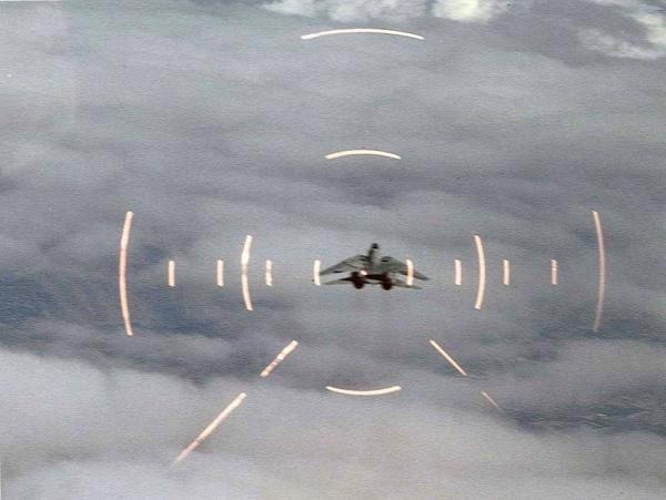
U.S. Navy Grumman F-14A Tomcat aligned in the HUD of another aircraft during air combat maneuvering, 2013. Image Credit: By U.S. Navy [Public domain], via Wikimedia Commons
A HUD is any transparent display that offers a pilot an unbroken view of key flight information, projected directly into the pilot's line of sight (e.g., just inside the windshield or on a screen) – this enables the pilot to keep their eyes focused outside the aircraft.
Although the display may only be a meter to a few centimeters from the pilot’s eye, the HUD’s virtual images can appear to be projected at an extended distance of several meters in front of the aircraft, meaning the pilot does not have to change focus to the HUD screen itself or to look elsewhere for critical information (such as an instrument panel in the cockpit).
Aviation HUDs have been developed so that flight information is projected onto the same visual plane as objects in the exterior environment, so pilots do not need to refocus their gaze when looking back and forth between projections on the screen and outside the aircraft.
Initially developed for World War II aircraft, rudimentary HUDs were used extensively in military applications throughout the 1960s. The first civil application of the technology was implemented in 1993.1
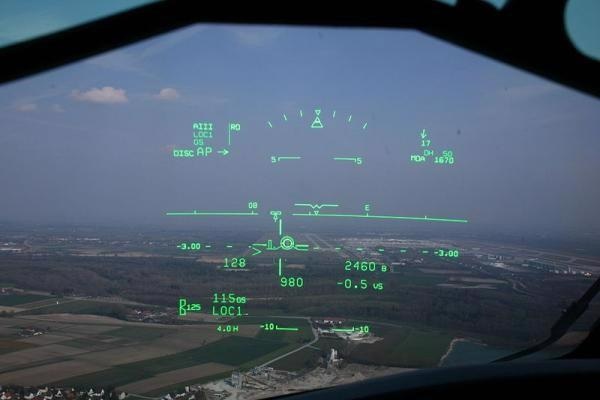
HUD in a Bombardier CRJ-200 displays the horizon line and other key flight information at 1000 ft. to assist with a smooth landing. Image Credit: By Shawn from Airdrie, Canada (CRJ HUD) [CC BY-SA 2.0 (https://creativecommons.org/licenses/by-sa/2.0)], via Wikimedia Commons
Now, these systems are frequently installed into both military planes and larger commercial jets. The Boeing 787 uses a Rockwell Collins head-up guidance system and was the first large commercial aircraft to be equipped with HUD as standard.
Traditional HUDs project virtual shapes and symbols that deliver information relating to navigation, the weather, and other key data. This information is collectively known as ‘symbology.’
The symbology can also include other statistics relative to aircraft position such as altitude, a horizon line, turn/bank & slip/skid indicators, radar data, heading & flight path and airspeed, alongside other data from the plane's avionics and instrumentation (military aircraft are equipped with HUDs that may display additional information such as an attack target, weapons status, etc.)
HUDs are especially useful in below-par visibility conditions. In fact, the Federal Aviation Administration (FAA) now allows pilots to make landings in situations with ‘no natural vision’ (zero-visibility) as long as an ‘enhanced flight vision system’ (EFVS) is installed onboard, for instance, an aircraft HUD system, or a helmet-mounted display (HMD) for the pilot.2
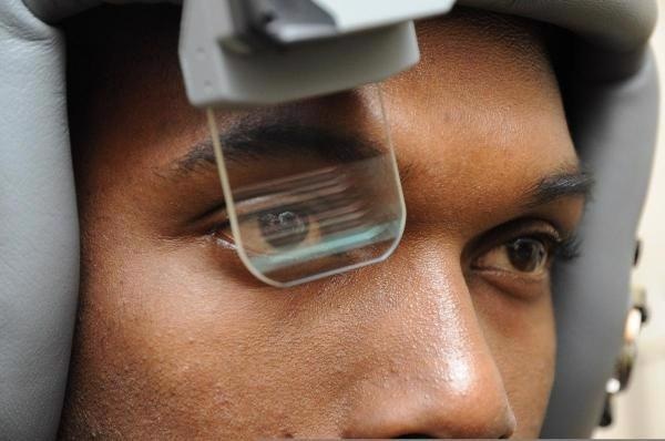
A Scorpion HMD system being tested by U.S. Air Force Senior Airman Dieri Dieujuste. The system provides targeting and tracking information in real time. Image Credit: By Staff Sgt. David Dobrydney [Public domain], via Wikimedia Commons
HUD System Components
To effectively operate, a HUD system usually includes the following components:
- A computer for the reception of data (including real-time metrics from the aircraft system sensors, avionics instrumentation and satellite data).
- A combiner, or a transparent display screen usually made of glass or plastic. The combiner reflects information towards the pilot’s eyes without impeding the exterior view through the windshield or obstructing the passage of ambient light.
- A control panel so that the pilot has the ability to select various display options and data to be displayed.
- A projector so that the assembled images can be projected onto the combiner screen. Modern HUD systems have terminated the use of overhead projector units and instead are able to project images directly on the display screen.
First-generation HUDs utilized a cathode-ray tube (CRT) display to display images on a phosphor screen. A number of HUDs still being used today are CRT displays, but over time the phosphor screen coating deteriorates.
To display images, the next-generation of HUDs incorporated the use of solid-state light sources, including light-emitting diodes (LEDs), modulated by a liquid-crystal display (LCD) screen. Today, many commercial aircraft make us of this type of HUD.
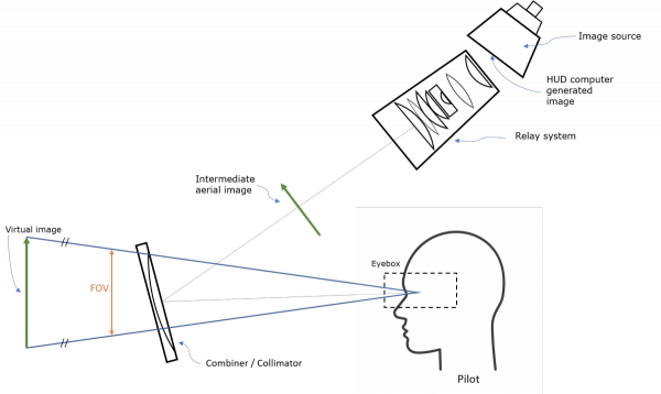
Schematic diagram of a conventional cockpit HUD. Image Credit: Radiant Vision Systems
Third-generation aviation HUDs use optical waveguides that generate images directly in the combiner, eliminating the need for a projection system. Some of the most advanced HUD systems utilize a scanning laser, which can generate images and videos onto a clear transparent medium, such as a windshield.
HUD manufacturers are also starting to work with imaging technologies like digital micromirror devices (DMD), liquid crystal on silicon (LCoS), and organic light-emitting diodes (OLED) to minimize the size, weight, and complexity of HUD systems.
To improve the display further, the next generation of HUD technology adds synthetic terrain or infrared video information as part of a broader category of EFVS that includes traditional HUDs.
A LightHUD® digital display by BAE Systems can be installed to upgrade aircraft with HUDs, with size and weight efficiency over older CRT HUDs. Image Credit: Radiant Vision Systems
Human Factors in Aviation HUDs
Assessing human factors is about understanding human behavior and performance. Across the aerospace industry, debates concerning human factors are often focused on the aspect of human error in accidents and system failures.
Here, ‘human factors’ is a reference to specific elements of human capacity and performance factors such as visual perception. Consideration of innate human characteristics and responses facilitates the optimal design of systems that will be used by humans (the discipline of human-centered design).
Thoughtfully designed equipment and quality components help limit human factors as a contributing factor in poor performance and accidents.
For humans, the eyes (and the visual processing centers and associated optic system of our brain) are the most crucial source of information we use to evaluate and understand the world around us. Human vision has propelled a great deal of cockpit technology evolution.
In contrast to the complicated, gauge-based systems of the past, the electronic flight displays of today’s modern airliners are testament to advances in human factors engineering.3 Some of the most key considerations relative to human factors include:
- Focus & Accommodation. For the eye to “register a sharply focused image, certain structural alterations are required depending on the focal length or distance to the object of interest. The process of adapting focal length from a distant object to a near point is known as visual accommodation and involves three separate but coordinated functions - lens accommodation, pupil accommodation, and convergence. The speed at which accommodation occurs varies between individuals and with age, but it is generally a split-second affair.”3
Thus, a display configuration requiring the pilot to switch focal point from near (display screen) to far (exterior landscape) could potentially impede the pilot’s performance, not improve it.
- Visual Attention. The brain has a limited capacity when simultaneously processing various amounts of visual information. The visual working memory helps process and buffer the information humans absorb, effectively ‘metering’ competing stimuli.
However, focusing on particular items also obstructs focus on others, which possibly results in ‘attentional blindness.’ This selectivity is crucial for a human’s ability to function in complex environments but can also be a potential danger when flying an aircraft.
“To efficiently attend to various information sources, and appropriately balance their time between focused and divided attention, pilots are taught the process of ‘scanning,’ or attending briefly to each information source sequentially in a systematic fashion.”3
HUD displays limit such complexity by overlaying visual information on to the exterior environment, making processing of both types of visual input at once much easier.

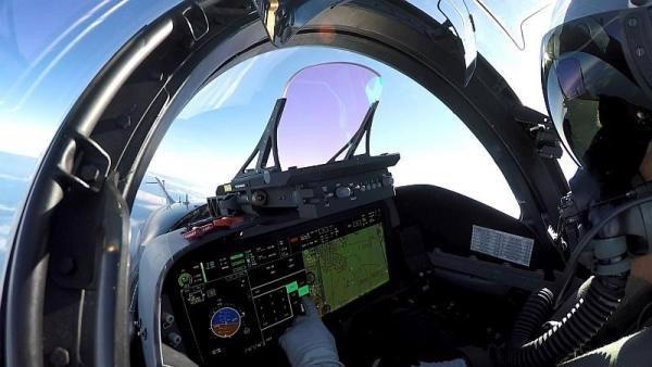
With so much occupying the pilot’s field of view on the instrument panel, HUDs can ensure they always remain focused on the most critical elements. Image Credit: Radiant Vision Systems
- Color and Contrast. Correct color and contrast values in a HUD display are vital for safety and usability in all operating conditions. The human eye is extremely sensitive to color and luminance (brightness).
The eye is more sensitive to contrast than absolute luminance. This enables humans to possess good vision over a wide range of lighting conditions. High contrast (for instance, black text on a white page) is more straightforward to discern than shades of gray.
Successive contrast is the effect on perception in a dynamic situation when the eyes shift between one or more objects or views in succession.
For instance, switching between looking at bright cockpit lights then moving the gaze to a dark sky causes reduced perception because the eyes take longer to adjust to the darker view. HUD systems generally use green light for their display symbology as the human eye is most sensitive to these wavelengths.
Design Factors
Assembling an effective HUD system heavily depends on the design of the display itself. Considerations about the form factor, lighting, size and more must be evaluated carefully. Factors include:
- Field of View (FOV) – FOV is the scope of the angle (vertical, horizontal and diagonal) captured by a display for transmission back to the pilot.
For instance, a combiner with a narrow FOV might show only a runway; a wider FOV could provide more information around the perimeter of the runway, which enables the pilot to see peripheral objects like other planes approaching from the side.
- Parallax – Due to the fact human eyes are separated by a slight distance, each eye receives an image slightly different from the other, which the brain combines to create binocular vision.
Parallax errors occur when the image generated on a HUD is not in eye-to-eye alignment. A HUD image must be clearly viewable by one or both eyes. This issue is usually addressed by collimation.
- Collimation – The human eye only has the ability to focus on one point at any given moment. Thus HUD images need to be collimated: the projected light rays need to appear infinitely parallel rather than appear to converge at a point on the physical display screen.
With collimation, there is no need for the pilot to refocus to view both projected symbols and the exterior environment since both appear on the same ‘infinite plane.’
In time-sensitive and safety-critical maneuvers such as landings, eliminating even the smallest amount of time it takes a pilot to refocus from the digital projection to the outside view can be critical. A collimator is a vital component of any optimized HUD system.
- Eyebox – To facilitate collimation and clarity of the display, the user’s eyes cannot be too far outside of the prime viewing position, which is referred to as the head motion box or ‘eyebox’ area of the HUD system.
Move too far left/right, up/down, and the image may be only partially displayed or even distorted. Modern HUDs allow some scope of movement across an eyebox around 5 inches lateral by 3 inches vertical by 6 inches longitudinally (front to back).
For a premium HUD, the pilot must be able to view the whole display as long as one eye is inside the eyebox.
- Luminance/contrast: A HUD must balance luminance and contrast in relation to ambient light conditions – sunlight, night conditions, weather, etc. – to ensure readability
- Boresight – Aircraft HUD components must be aligned precisely with three axes of an aircraft so that data on the display aligns with the plane’s actual position in space – that is, relative to the artificial horizon.
This alignment process is known as boresighting. This is generally done to a precise accuracy of ±7.0 milliradians (±24 minutes of arc) and may fluctuate across the HUD’s FOV.
- Scaling – The images generated on the HUD must be scaled to overlay the outside view with a 1:1 relationship relative to the flight path (pitch and yaw scaling, landscape details, etc.).
“For example, objects (such as a runway threshold) that are 3 degrees below the horizon as viewed from the cockpit must appear at the −3° index on the HUD display.”4
Quality Regulations
The visual performance of HUD systems is crucial due to them being operational in real-time flight situations. The FAA has put in place a number of Advisory Circulars on topics relative to HUD displays and electronic flight displays.
Among numerous operational considerations, the agency specifies parameters related to a display’s size, resolution, reflectivity/glare, symbology line width, response, refresh rate and update rate, contrast ratio, chromaticity, grayscale, defects (such as element defects and stroke tails), luminance (in all light conditions) and the size of the flight deck viewing envelope.
For a comprehensive list of specifications, refer to the FAA Advisory Circulars:
- AC-20-167A – Airworthiness Approval of Enhanced Vision System, Synthetic Vision System, Combined Vision System and Enhanced Flight Vision System Equipment
- AC-25-11B – Electronic Flight Displays
- AC-25_1329-1C – Approval of Flight Guidance Systems
- AC 90-106A – Enhanced Flight Vision Systems
Testing Head-up Display Quality
A display testing regimen that is both robust and meticulous must be put in place by aerospace manufacturers to ensure that HUD systems and equipment have addressed the design and functional considerations and are effectively developed to mitigate human factors and adhere to FAA guidelines.
Methodical design and quality control inspection guarantees HUD projections that are appropriately clear and aligned for in-focus binocular viewing and that light and colors are bright enough to be distinguishable from surroundings in any lighting condition.
Low-quality HUD projections put aircraft at risk, since operators may not be able to interpret objects in the viewing area of the display that are poorly projected, resulting in loss of key environmental data such as navigation, object proximity, and other alerts, as well as misinterpretation and distraction.
An optical measurement device and complementary test and measurement software are utilized to inspect HUD projections at a number of points within the eyebox area (to represent the scope of possible viewing angles) in order to evaluate these elements accurately.
Radiant Vision Systems offers the leading solutions for traditional display, near-eye-display (NED), and HUD testing in aerospace, automotive, and consumer electronics industries, with benefits that accelerate testing speed and simplicity.
When compared to test methods that utilize spot meters (for example, spectroradiometers) or conventional human inspection, Radiant’s all-in-one HUD test platform is an automated system that depends on imaging to assess an entire display for all photometric (color, contrast, light) and dimensional requirements (defects, distortion, ghosting) in sequence.
Radiant’s ProMetric® Imaging Photometers and Colorimeters have been implemented in testing environments to evaluate see-through display technologies from OLED to waveguide, utilizing a wide range of projection methods.
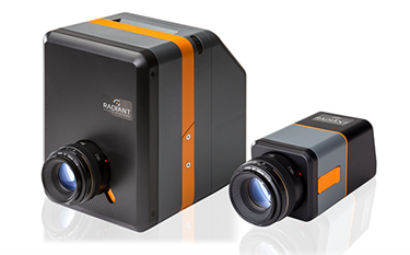
Radiant's ProMetric cameras are scientific imaging systems with optical components that simulate human visual perception of light and color (based on standard CIE color-matching functions). Systems include benefits for automated HUD measurement such as electronic lenses, dynamic calculation of virtual image distance, and software with HUD test library, API, SDK, and automated pass/fail test sequencing. Image Credit: Radiant Vision Systems
Radiant software has been designed with a HUD test library that includes contrast, chromaticity, distortion, ghosting, eyebox, luminance, modulation transfer function (MTF), uniformity and other HUD visual performance parameters.
The software operates with a ProMetric imaging system, available in a range of high-resolution options, and designed to simulate the colorimetric and photopic response of the human eye.
Radiant cameras are equipped with electronic lenses and software that offer remote focus and aperture adjustment. The combination of these technologies supplies the fastest and most precise evaluation of virtual images projected on an infinite plane, such as HUD symbology.
Radiant imaging colorimeters map points of interest to projected symbols and give measurements with minimal adjustment while recording object distance, size, and scale at any working distance to guarantee visual performance.
Want to know more? Radiant imaging photometers and colorimeters can solve several test and measurement challenges across the aerospace industry. See a demo of Radiant’s automated HUD test and measurement solution.
For additional information, visit: www.RadiantVisionSystems.com.
Citations
- "Head-Up Display" on SkyBrary, https://www.skybrary.aero/index.php/Head_Up_Display
- Refer to FAA Advisory Circular 90-106A, issued 3/2/17
- Nichol, Ryan J., “Airline Head-up Display Systems: Human Factors Considerations”. International Journal of Economics and Management Sciences, 4:248, May 3, 2015. https://papers.ssrn.com/sol3/papers.cfm?abstract_id=2384101
- "Head-Up Display" on Wikipedia, https://en.wikipedia.org/wiki/Head-up_display
References

This information has been sourced, reviewed and adapted from materials provided by Konica Minolta Sensing Americas.
For more information on this source, please visit Konica Minolta Sensing Americas.