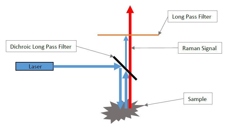
Raman spectroscopy is used to detect and identify a material by investigating its molecular rotation and vibration. Normally, laser light is incident upon the material and the scattered light is measured.
The excitation source (laser line) intensity is usually 6 to 8 orders of magnitude more than the Raman scattered signal. Because of this, edge pass or notch filters must be used This is highlighted in the figure belowto block the Rayleigh scattered laser light while ensuring that the red-wavelength shifted (Stokes) and/or the blue-wavelength shifted (Anti-Stokes) Raman scattered signal is transmitted.
This article begins by defining some key terms used to refer to Raman edge (or notch) filters. Next, a discussion takes place on how to make best use of the edge pass filter to make certain that the required optical performance is achieved in the proposed application.
The range of parameters which influence the measurement of edge pass filter transmittance are outlined, including polarization of light, angle of incidence, light cone incident upon the filter, and variation in laser line wavelength.
Optical Density
Optical density (OD) acts as a measure of the blocking capability of an optical filter. As light passes through the filter, some is transmitted, with the rest being either scattered, reflected or absorbed.
Optical density considers every type of light attenuation and is defined as:
OD = — log10T
where ‘T’ is the transmittance of a filter. The OD value of a filter is numerically equivalent to  of the filter’s transmittance when specified in dB.
Examples of different OD levels compared with T[dB] for a Long-Pass Filter (LPF) are shown in the figure below. Unless otherwise indicated, this and other figures assume collimated, monochromatic light incident upon the filter with a negligible instrument (detector) resolution.
![Example of a typical Long Pass Filter (LPF) shown with the filter transmittance in dB and linear scales. Different OD levels corresponding to T[dB] are also shown.](https://d36nqgmw98q4v5.cloudfront.net/images/Article_Images/ImageForArticle_1803_15876259453951373.png)
Example of a typical Long Pass Filter (LPF) shown with the filter transmittance in dB and linear scales. Different OD levels corresponding to T[dB] are also shown.
Edge Steepness
An edge pass filter’s edge steepness is characterized as the spectral width (specified in units of ‘%’, ‘nm’ or ‘cm-1’) between two points on the edge pass filter’s slope.
As such, the smaller a filter’s edge steepness, the sharper the transition from passing light to blocking it. This also makes it harder is to fabricate the filter, because of the need to maintain a low passband ripple.
It should be noted that the ‘spectral edge’ of an edge pass filter is normally defined as the wavelength where the filter transmittance = -3 dB (50%).
In the figure below, the edge steepness is defined (as normal) as the spectral width between the -3 dB (50%) point of a filter and its -60 dB (6 OD) point. The latter is typically the filter’s minimum allowable OD at the laser line wavelength.
The filter’s edge steepness could also be defined in a different way depending on the application in question; for example spectral width could be between 90% and -60 dB of the filter.
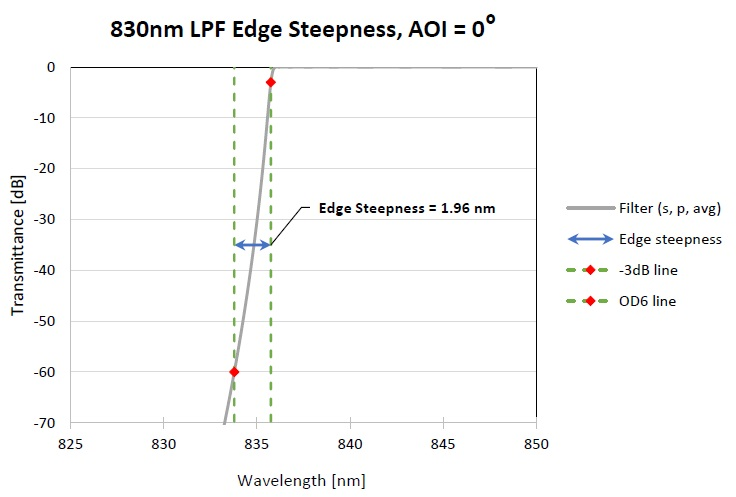
Figure showing how ‘Edge Steepness’ of a LPF is typically defined (in this case, between -3 dB and -60 dB transmittance levels).
Cut-Off / “OD Blocking at the Laser Line Wavelength”
An edge pass filter’s cut-off is defined as the spectral width (specified in units of ‘%’, ‘nm’ or ‘cm-1’) between the laser line wavelength and the wavelength that corresponds to the 50% transmittance (-3 dB) point of the edge pass filter’s transmittance spectrum.
The OD blocking at the laser line wavelength specifies the minimum desired blocking that needs to be achieved at the laser line (LL) wavelength, λLL. Generally speaking, for given cut-off and desired OD blocking levels at the laser line, the smaller the cut-off value, the ‘sharper’ the filter, and the more challenging it is to fabricate it.
The cut-off value is relative to the laser line wavelength while the edge steepness is an innate property of the filter. Attaining specific cut-off and OD blocking at the LL necessitates reaching the filter’s steepness while simultaneously positioning the -3 dB edge relative to the laser line wavelength.
As a result, cut-off is a more demanding specification, while being more relevant to the application.
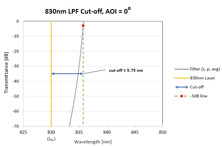
Figure showing the typical definition of the Raman filter ‘cut-off’ specification. In this example, the cut-off is 5.75 nm or it can also be specified as 82.9 cm-1.
Effect of Angle of Incidence (AOI)
AOI represents the angle between the incident beam and the normal surface of the filter. An AOI of 0° may be described as ‘normal incidence’, while with any non-zero (such as non-normal or oblique) AOI, the filter’s spectral edge will shift towards shorter wavelengths.
The downshift in wavelength for a specific AOI is dependent on both design and light polarization. Light may be linearly polarized (s- or p-polarized), or a mixture of linearly polarized light. The filter’s performance at non-normal AOI will therefore be contingent on the degree of polarization of the light.
In particular, the wavelength downshift with AOI will vary between s- and p-polarization of light. This phenomenon may result in polarization splitting.
Increasing the AOI reduces the filter cut-off as well as the OD of the filter at the laser line wavelength. This occurs as the spectral edge of the filter is shifted closer to the laser wavelength. This is shown in the figure below.
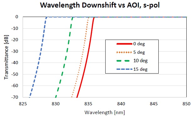
Figure showing wavelength downshift of an 830 nm LPF versus AOI for s-polarized light.
The next figure illustrates the impact of altering the AOI of an 830 nm LPF on the subsequent change in the cut-off value and the filter OD blocking at the laser line wavelength.
Here, the OD blocking of the filter at the laser line wavelength rapidly reduces from 6.2 OD to 4 OD as AOI changes from 0° to 4°, respectively. The same AOI change sees the cut-off value reduce by a factor of 2.
![Figures showing how the cut-off off a filter and the OD [at the laser line wavelength] varies with the angle of incidence (AOI) of s-polarized light on the filter.](https://d36nqgmw98q4v5.cloudfront.net/images/Article_Images/ImageForArticle_1803_15876260675505537.png)
Figures showing how the cut-off off a filter and the OD [at the laser line wavelength] varies with the angle of incidence (AOI) of s-polarized light on the filter.
Polarization Splitting
As the AOI rises from normal incidence, the filter edges shift to shorter wavelengths (‘blue-shift’). The edges for s- and p-polarizations shift various amounts leading to polarization splitting. For an LPF, the p-polarized spectral edge is blue-shifted more than the s-polarized spectral edge. For a short-pass filter (SPF), the s-polarized spectral edge is blue-shifted more than the p-polarized spectral edge.
Polarization splitting causes a flat ‘shelf’ in the spectral response of ‘average’ or ‘un-polarized’ light; this being a 50% mixture of s- and p-polarized light. This lowers the effective edge steepness and the cut-off of the filter.
In the figure below, the transmittance of an LPF filter is displayed for light incident at an angle of 10° for s-, p- and average-polarized light. The polarization splitting is apparent where the p-polarized light is shifted further in contrast to the s-polarized light. With average polarization of light, the flat shelf is at a -3 dB (50%) level.
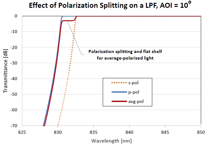
Figure showing the change in transmittance of a LPF filter for different polarization states of light (at an AOI of 10°).
The flat shelf transmittance level fluctuates with various mixtures of polarized light in the incident light; for example, for a mixture of 80% s-polarized light and 20% p-polarized light, the transmittance of the shelf would be less than 20%.
This is highlighted in the figure below. Measured from the laser line wavelength to the 50% transmittance level, the filter cut-off is 45 cm-1 for the average polarization beam (as anticipated) but it is 57 cm-1 for the partially s-polarized beam and 29 cm-1 for the partially p- polarized beam.
In all cases the filter is the same, but the cut-off differs due to the polarization of the probe beam. Consequently, it is essential to use the filter with the polarization state that it was intended for.
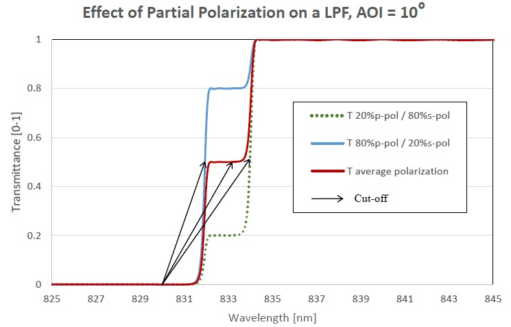
Figure showing, for a 830-nm LPF at AOI=10°, how the change in polarization in the incident light can effect the apparent filter cut-off and the ‘flat-shelf’ transmittance level.
Effect of Laser Wavelength
As discussed, the filter cut-off is the wavelength difference between the laser line wavelength and the wavelength that relates to a defined transmittance point (usually T=50% point) on the filter spectrum.
Raman edge filters designed for specific laser wavelengths will make use of variations in the actual laser wavelength used, as this will impact on the filter cut-off and the OD blocking at the laser line wavelength.
As such, it is vital that designs take into account potential variations in the laser wavelength being used in a particular application when defining the requirements of a Raman edge filter.
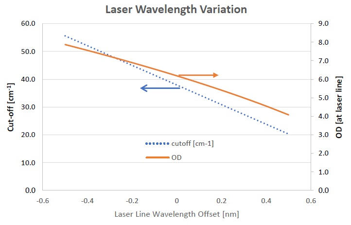
Figure showing how deviations from the laser line wavelength, for which a LPF was designed for, effects a LPF’s cut-off and OD blocking at the laser line wavelength being used. In this example, a deviation of +0.2 nm in the laser linewavelength results in the OD blocking dropping from 6.2 OD to 5.2 OD while the cut-off decreases from ~38 cm-1 to 30 cm-1.
To provide an example, where a Raman LPF is installed in instruments which may see a significant variation in the laser wavelength (for example, more than ±0.1 nm), the LPF filter will not function as intended even though it may otherwise meet all the defined specifications.
Effect of a Light Cone
In earlier figures, it was presumed that the light on the filter was collimated. However, for the majority of applications, the light incident on the filter is a combination of different light rays arriving with different angles of incidence and relative intensities.
This example can be modeled by presuming a light cone is incident up a filter with different relative intensities. It is possible to define a Cone Half Angle (θCHA) to identify the angular spread of the light for a non-collimated light source like an LED.
The angular spread may be modeled as a Gaussian profile with a θCHA defined as the angle at which the normalized light intensity is  of the maximum intensity.
The following figure displays a Gaussian profile light source with θCHA=5.5°.
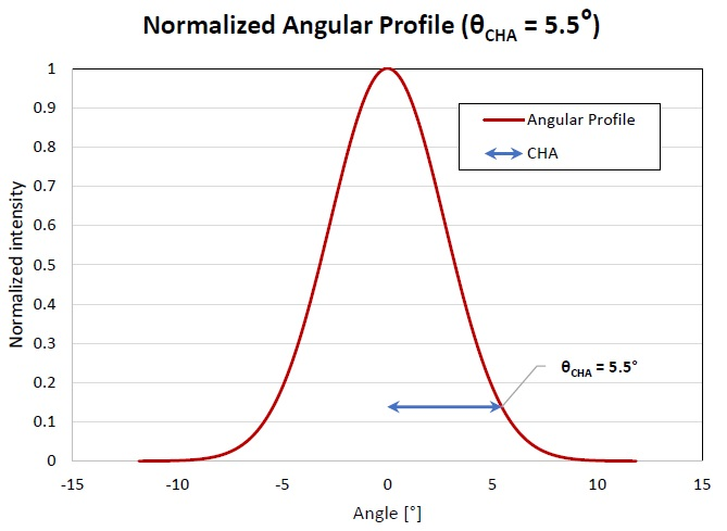
Figure illustrating a possible line cone having a Gaussian intensity profile.
The next figure illustrates the transmittance of an LPF when a light cone with a Gaussian profile based on a θCHA=5.5° - and various polarization states - is incident upon the filter.
As can be seen, the presence of non-collimated light can cause a noteworthy change in the measured transmittance of the LPF, prompting an increased edge steepness and decreased OD blocking at the laser line.
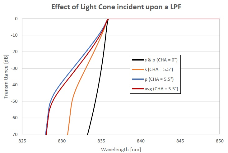
Figure showing the transmittance of LPF for a collimated beam (θCHA=0°) and for a light cone (θCHA=5.5°) for s-, p- and average-polarized light.
The next figure illustrates the way in which altering a light cone’s θCHA from 0° (collimated beam) to 4° incident on an LPF changes that LPF’s cut-off and OD blocking at the laser line. In this instance, the 830 nm LPF was intended to work at an AOI=5° in average polarized light.
As highlighted above, the cut-off does not alter significantly, because the -3 dB wavelength does not change much while the light cone angle increases. However, the OD blocking at the laser line is affected to a high degree, varying from 6.2 OD to less than 5 OD when the half-cone angle is larger than 1.5°.
As can be seen, it is essential to have a good appreciation of the light cone incident upon a Raman edge filter in order to achieve the required performance. In cases where there is a significant half-cone angle, it may be advantageous to opt for a less steep edge filter slope (with a higher filter cut-off) to guarantee that the Raman filter laser line blocking is preserved.
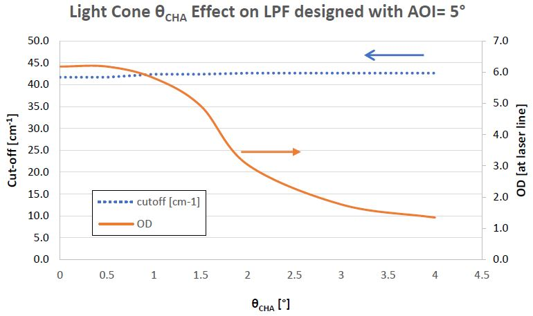
Figure showing, for a 830 nm LPF designed to be used at a AOI of 5° for average polarized light, how the cut-off and OD blocking at the laser line is affected by the half-cone angle of a light cone incident up on the LPF.
Effects of Wavelength Instrument/Detector Resolution
The theoretical transmittance curves of the filters discussed previously assume that the detector/instrument wavelength resolution is negligible. But, optical metrology devices may utilize a wavelength resolution between 0.1 nm and 2.0 nm to sufficiently improve the signal to noise (S/N) ratio, particularly when measuring the OD blocking of a filter.
Using a non-zero instrument resolution on the measurement of an LPF means that the transition from passband to blocking becomes ‘rounded’. The extent of this rounding is proportional to the resolution bandwidth that is used, meaning that a higher instrument resolution (or bandwidth) results in increased rounding.
For an LPF designed for a AOI=0°, there is considerable rounding in the LPF measurement as the instrument resolution (bandwidth) is altered from 0 nm to 2 nm. At a resolution bandwidth of 2 nm however, the LPF transmittance in the blocking spectral region seems to be higher. This can be seen in the figure below.
It is important to note, that this occurs due to a measurement artifact which is a result of a non-zero instrument resolution. The LPF filter shape is fine in this instance, and this can be substantiated if measured with a small instrument resolution (bandwidth).
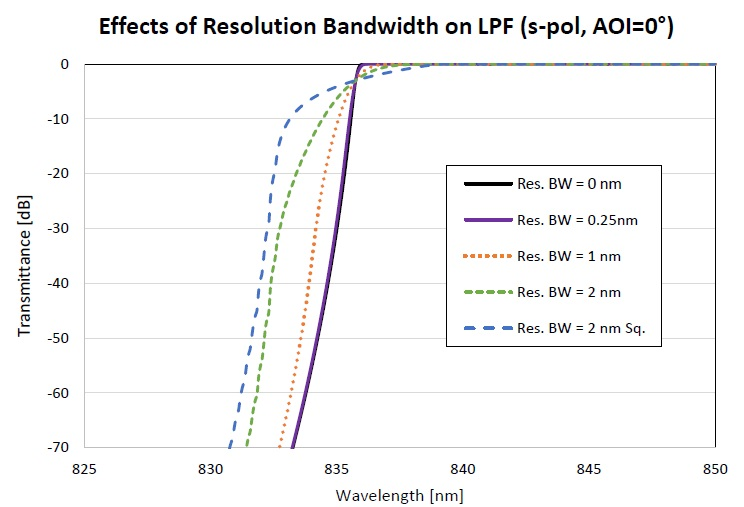
Figure showing the transmittance of a LPF when measured with different instrument resolutions.
Measurement of OD Blocking Level
It can be fairly difficult to precisely measure the Optical Density (OD) of a filter down to 6 to 8 OD. If not approached correctly, measurement artifacts can make it seem like a Raman edge pass filter is unable to meet the OD blocking specification at the laser line.
Accurate blocking measurements can be acquired through various different means. The best, and most simple approach is to make use of a tunable laser light source for direct measurement. Alternatively, if a single wavelength laser is all that is available, it is possible to measure the transmittance by angle tuning the filter.
It is possible to use commercial spectrophotometers, but because these instruments use a white light source, they generally possess a noise floor anywhere from 2 OD to 7 OD (-20 dB to -70 dB). This is, of course, dependent on the instrument bandwidth selected.
Even if the filter is capable of blocking lower than this particular noise floor level, it may not be feasible to demonstrate this with commercial spectrophotometers. Plus, in order to reach a low noise floor (>6 OD), a large instrument resolution must be used. This in turn may impact upon the measured slope of the edge pass filter, resulting in another type of measurement artifact.
The figure below illustrates the measurement of an Iridian Nano-Edge LPF with a tunable laser source.
It highlights that there is a high level of agreement with the expected design (theory) performance. However, ff this filter was measured with a commercial spectrophotometer, then the blocking level at the laser line would have been shown to be much less – around 4 to 6 OD, depending on the instrument resolution.
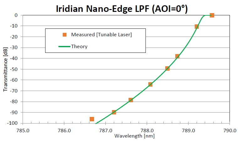
Figure showing the measured transmittance of Iridian Nano-Edge LPF using a tunable laser (orange squares) with AOI=0°. The theoretical data for the edge pass filter is also shown (green curve). As can be seen, there is an excellent agreement between theory and measurement down to around -90 dB (9 OD) after which the measurement setup with the tunable laser hits a noise floor around -95 dB.
To measure the transition from the passband to blocking spectral regions, a broadband white light source can be used with an OSA. To accurately measure this, the instrument resolution should be made as narrow as possible.
The figure below displays the measured data of the same Iridian Nano-Edge filter as shown in the previous figure. The instrument resolution here was 0.05 nm and the light beam possessed a cone half-angle of ~2°. With this instrument resolution, the OD noise floor is around 2 OD and, as highlighted here, there is good agreement between the OSA measurement and the anticipated performance of the design.
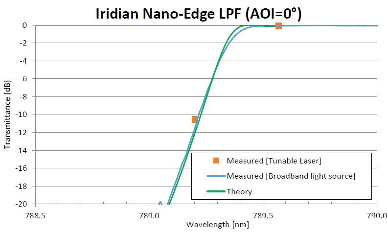
Figure showing the measured transmittance of Iridian Nano-Edge LPF using a OSA with a broadband light source (instrument resolution was 0.05 nm and a light beam had a cone angle of 2° (blue curve). The theoretical data for the edge pass filter is also shown (green curve). As can be seen, there is a very good agreement between theory and measurement down to around -20 dB (2 OD) after which the measurement setup hits a noise floor around -22 dB.
Cumulative Effects
The cumulative effects of all the parameters described above - AOI, polarization, instrument resolution, half-cone angle and laser wavelength variation - may affect the performance of the Raman edge pass filter.
These are not necessarily intuitive, and, for example, even minor changes in these individual parameters can result substantial overall change in the filter’s spectral performance.
In general, any combination the above effects will see measured edge steepness will decrease while the cut-off of the filter increases. Additionally, the transition edge will be more rounded, shifting towards shorter wavelengths, and the OD blocking level at the laser line will decrease.
All these changes will occur, even though the edge pass filter performance remains as specified for a collimated light beam that is operating with the design laser line wavelength.
This phenomenon can be seen in an 830 nm LPF design filter as shown in the figure below. The ‘blue’ curve illustrates the expected filter performance for a well-collimated beam at AOI=0°. As can be seen, it shows negligible resolution bandwidth and the laser line wavelength is as designed.
The ‘orange’ curve highlights the expected filter performance when the light incident upon the filter is a light cone with θCHA=5° (at an AOI=0°), with a 1.25 nm resolution bandwidth. The laser line wavelength was +0.2 nm higher than the desired laser line wavelength, with these values corresponding to a potential application of the LPF.
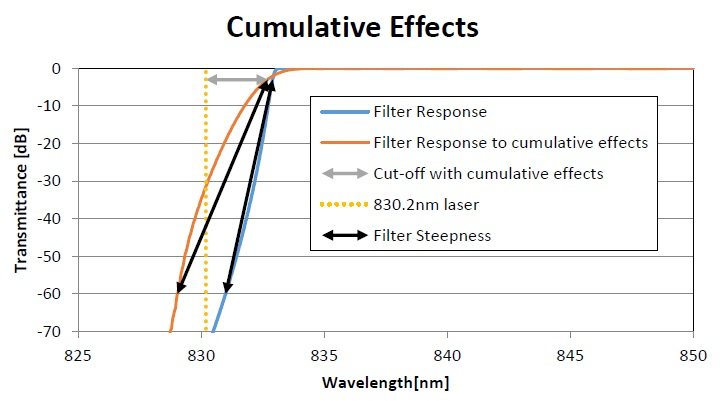
Figure showing transmittance of LPF designed for a well-collimated beam (AOI=0°, θCHA=0°, resolution bandwidth=0 nm, laser line wavelength offset = 0 nm) – ‘blue’ curve and its use in an application with a divergent beam with the laser line wavelength being different than specified (AOI=0°, θCHA=5°, resolution bandwidth=1.25, laser line wavelength offset =+0.2 nm) – ‘orange’ curve). Note that as used in this application, the OD blocking is ~3 OD instead of the expected >7 OD.
The result in this instance is that the filter cut-off, OD blocking level and edge steepness differs considerably between these two application examples, as illustrated in the table below.
Table showing the large change in laser line blocking level, cut-off and edge steepness as the light cone half-angle is changed; AOI is changed; laser line wavelength offset is introduced; and there is a non-zero instrument bandwidth.
| Specification Parameter |
Filter performance, using as-designed |
Filter performance with light cone (θCHA=5°), instrument resolution
of 1.25 nm and laser line wavelength offset (+0.2 nm) |
| Laser Line Blocking |
7.8 OD |
3.1 OD |
| Cut-Off |
2.9 nm
(42 cm-1) |
2.5 nm
(36 cm-1) |
| Edge Steepness (6 OD to 50%) |
1.9 nm |
3.7 nm |
It is, however, possible to design the LPF to allow for the light cone incident on the filter. This configuration is displayed in the figure below, with the blocking level now being better than 6 OD at the laser line wavelength.
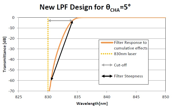
Figure showing transmittance of LPF designed for (AOI=0°, θCHA=5°, resolution bandwidth=1.25 nm) – ‘orange’ curve. Max cut-off is 4.2 nm (61 cm-1), minimum 6 OD blocking.
Summary
The aim of this article was first to make sure that that the technical definitions used when describing a Raman edge pass filter are clear and easy to understand. It then aimed to help users understand how a filter’s measured performance will very much depend on how it is used in an application.
Selecting the ideal edge steepness, filter cut-off, filter AOI and OD blocking level will depend firstly upon the properties of the light incident upon the filter (half-cone angle, polarization), secondly upon any variation in the laser line wavelength and finally, upon the detector resolution (bandwidth) utilized in the application.
Finally, if measuring the filter on a spectrophotometer in order to validate its performance, it is crucial the ensure a good understanding of the effects of the spectrophotometer light cone, polarization state and the instrument resolution (bandwidth) on the measured transmittance. This is important, as measurement artifacts can make it appear that an edge pass filter does not meet specification).

This information has been sourced, reviewed and adapted from materials provided by Iridian Spectral Technologies.
For more information on this source, please visit Iridian Spectral Technologies.