As the power of laboratory lasers increases, aspheric lenses and mirrors have been pushed to deliver extremely high intensities.
Manufacturing a steep, off-axis parabolic (OAP) mirror is immensely challenging. Asphericity is a direct measure of the degree of difficulty of its manufacture. Asphericity is a function of the mirror as a whole and is dependent on the diameter, off-axis distance, and assumed focal length compared to a “best-fit sphere”.
Generally, OAP mirrors with an asphericity of 1 mm or more and that also maintain other, high-quality specifications, are considered to be exceptionally difficult to produce. Key measurement specifications include slope errors, surface quality (scratch/dig), and surface accuracy (effectively wavefront error).
Asphericities are well below 1 mm for most applications, and the desired specifications are limited to a good surface accuracy (typically λ/10 P-V at 633 nm). For less demanding applications such as these, the surface quality of an OAP mirror is often a cosmetic need. Additionally, for these applications, slope errors rarely require specification because they generally have no effect on overall performance.
However, for high-power laser applications that are intended to push barriers and deliver an intensely focused, well-designed beam, the OAP mirror needs to be fast. For these applications, asphericity may be significantly higher than 1 mm.
Having a high asphericity means that the focused laser spot will only be a few microns in diameter. The tightly contained, focused spot is achieved using mirrors that demonstrate excellent surface accuracy because they have been appropriately mounted and aligned. Small slope errors on OAP mirrors mean that the spread of light is held to an absolute minimum around the beam. This is crucial because even a tiny perturbation in the local field may disturb the extraordinary balances needed during nuclear capsule compression.
A good mirror surface additionally reduces the possibility of coating damage caused by diffraction effects from fine digs or scratches on the surface. Such effects would increase the chances of local hot spots manifesting in the vicinity of defects. This is due to the high intensity and coherence of the light used, as well as the potential for constructive interference that could occur.
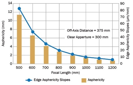
Figure 1. OAP asphericity and edge slopes increase dramatically as focal length decreases. Image Credit: Optical Surfaces
During the manufacturing process, performance factors compete with each other. Achieving all three factors simultaneously is challenging, especially for a highly aspheric mirror. An analysis, shown in Figure 1, shows how rapidly the asphericity (and edge asphericity slopes) grow in an OAP mirror of a given aperture, as the focal length decreases.
For example, if an OAP mirror with a focal length of 700 mm is used, the corresponding asphericity will be in excess of 4 mm, with rapidly growing slopes as the edges farthest from the optical access are approached. Smaller and smaller tools are needed to improve overall surface accuracy and mirror shape with traditional lap polishing. Small tools allow effective work through the rapidly changing slopes. However, during this process strong local imprints (slope errors) are generated and these can only be removed using larger tools. The need to change between small and large tools creates a strong competition between the continuous improvements of either of the two parameters desired.
Moreover, the need to keep the surface virtually free of digs or scratches means that the risk of prolonged production time is significantly increased. Removing defects could compromise or even ruin the smoothness and shape of the surface. This translates into lost production time of days or weeks.
Microroughness
Another crucial quality factor in OAP mirror production that needs to be considered and controlled is microroughness. It concerns features even smaller than slope errors and is often expressed in terms of root mean square (rms), after integrating over spatial periods, that are usually less than 0.25 mm. When produced, such features tend to create effects that are similar to mild scattering.
It is not well understood how microroughness can be controlled intentionally during manufacturing. However, very good results that consistently do not exceed 1 nm rms have been produced by the pitch-polishing technique. Using data collected on OAP mirrors, it can be suggested that some of the higher microroughness values close to the 1 nm rms mark might relate to higher asphericity.
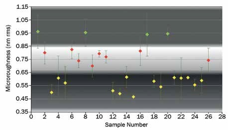
Figure 2. Microroughness distribution using pitch polishing. Note: Color bands help with visibility and assist with conceptual dividers between clusters. Image Credit: Optical Surfaces
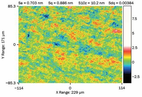
Figure 3. Typical microroughness surface map obtained using WLI; 50× magnification. Sa: arithmetical mean height of the surface; Sq: rms height of the surface; S10z: 10-point height; Sdq: density of peaks. Image Credit: Optical Surfaces
A correlation to material chosen for the OAP mirror substrate has not been found when looking at microroughness data. A randomly selected distribution of several microroughness measurements on a selection of precision optics performed over the past few years is shown in Figure 2. For comparison, a typical surface map measurement obtained using white light interferometry (WLI) is shown in Figure 3.
Materials and Coatings
With regards to material selection for OAP mirrors for high-power laser applications, a near zero- or zero-expansion substrate such as CLEARCERAM-Z (HS), ZERODUR, NIFS-I or Corning 7980 would be appropriate. Some high-power laser facilities prefer fused silica or very high-peak, extremely short power pulses. This is because of a presumed better response against “neutron activation” despite a slightly poorer (although still excellent) thermal response. Some coating suppliers suggest that coating adhesion on fused silica OAP mirrors may be better, however not all suppliers agree.
The most obvious choice when considering a coating for very high-power applications is an ultrahard multi-layered dielectric (MLD) coating. This is due to the high reflectance of the coating over a selected spectral range and, most importantly, due to the fact that it can be designed to withstand very high-power laser-induced damage thresholds (LIDTs).
It is also important for a very fast pulsed laser to achieve low GDD (group delay dispersion) values. GDD is used for characterization of layered mirrors when group velocity dispersion (GVD) is not particularly well designed, but the chirp induced after bouncing off the mirror can be characterized well. GDD is expressed in fs2 and provides a measure of the chromatic dispersion that is induced by the coating stack. The concern here surrounds the reflection of the mirror rather than transmission characteristics and so the substrate properties have no impact.
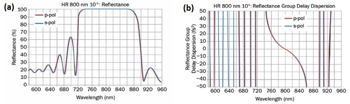
Figure 4. MLD coating, center wavelength 800 nm (a); standard type: S-shape GDD (fs2) response (b). R: high reflectance; p-pol: P-polarization (tangential component); s-pol: S-polarization (sagittal component). Image Credit: Optical Surfaces
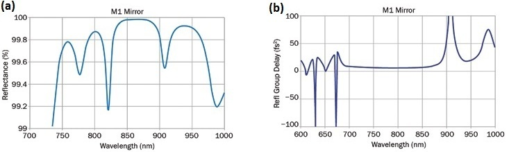
Figure 5. MLD coating, center wavelength 800 nm (a); special type: flat GDD (fs2) response (b). Image Credit: Optical Surfaces
For a top-quality OAP mirror, the ultimate goal is to keep GDD as low as possible, within ±50 fs2 for all wavelengths within the bandwidth around the center wavelength. The latter is harder to achieve in non-metallic coatings like MLDs since they require a carefully designed stack composed of more layers than usual, as well as having tight manufacturing tolerances. Balancing these demands with the fluctuations in reluctance as a function of wavelength results in a considerable coating cost rise. Two possible options in coating design are shown in Figures 4 and 5.
Focusing Lenses
Many of the challenges and considerations described for OAP mirrors apply to focusing lenses for high-power applications. However, there are a few notable differences. For focusing lenses, the required levels of asphericity and therefore degree of manufacturing difficulty, are often much less than the corresponding OAPs. However, there is still a catch.
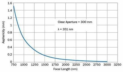
Figure 6. A focusing lens’ asphericity against focal length. Image Credit: Optical Surfaces
Focusing lenses are typically used with multiple beam lines. In the case of the U.S National Ignition Facility (NIF), there are as many as 192 beam lines. Consequently, these demanding lenses need to be manufactured simultaneously (as opposed to one very difficult OAP). A plot of asphericity versus lens focal length at 351 nm is shown in Figure 6. This allows for a direct comparison with the OAP examples previously described.
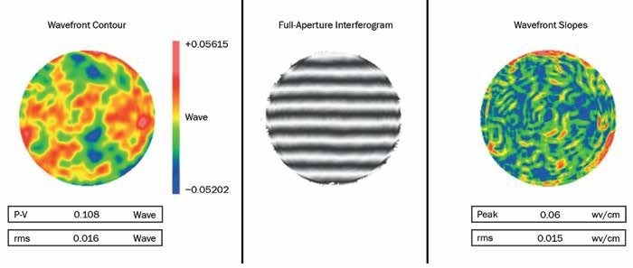
Figure 7. Focusing lens, f ~ 1200 mm, diam = 350 mm, asphericity ~ 0.4 mm. Image Credit: Optical Surfaces
High specifications for the slope errors, wavefront errors (WFE) in transmission, surface quality, and microroughness below 1 nm rms are equally important for focusing lenses as they are for OAP mirrors. The WFE and slope errors (in terms of waves) on a high-power laser focusing lens produced using a traditional pitch-polishing technique and tested at 633 nm, are shown in Figure 7. This lens has an asphericity around 0.4 mm, a diameter of 350 mm and a focal length of around 1200 mm.
Additional care should be taken during the manufacturing of focusing lenses for high-power laser applications despite the similarities in performance requirements with OAP mirrors. For example, because these optics are used in transmission, extra precaution needs to be taken to prevent microcracks developing under the polished surface (subsurface damage).
These microcracks, which may extend to as little as a few microns under the surface, are not directly visible unless the surface is chemically etched to remove the upper layer, so revealing the damage. Even then, a microscope is needed to observe their structure and extent. It is vitally important that these microcracks are kept to a minimum.
The lenses may shatter when the high-intensity pulses go through the glass if the subsurface damage is extensive. The lifespan of the focusing lenses may also be reduced significantly. It is important to proceed gradually through the smoothing grades, and with the progression to finer grades, to make sure that sufficient material is removed to reverse the potential damage caused by the previous grades. This helps to avoid subsurface damage.
Although hard dielectric coating is commonly used for OAP mirrors, sol-gel type of coatings are often preferred by high-power laser facilities for coating focusing lenses. Sol-gel type coating has high LDT and good antireflective (AR) properties. Most importantly, it is relatively easy to remove if damaged, and this allows for recoating. With hard AR coatings it is not possible to recoat. However, these surfaces can withstand much longer periods of laser impact.
Many leading laser facilities like Orion and NIF have developed their own sol-gel coating processes. They have internal facilities which can recoat within a few days, which provides greater autonomy and flexibility. This coating process involves the immersion of the lens within a suspension solution, drying and forming a gel-like substance on the surface. The coating is chemically processed to make it harder and enhance its properties.
Acknowledgments
Produced from materials originally authored by Aris Kouris from Optical Surfaces Ltd, originally published in Photonics Spectra (September and October 2019 issues).

This information has been sourced, reviewed and adapted from materials provided by Optical Surfaces Ltd.
For more information on this source, please visit Optical Surfaces Ltd.