There is a wide range of measurement systems available for characterizing MEMS devices optically. These measurement systems are varied technologies available which can measure lots of divergent physical properties (these may include film thickness, dimension, cross section, step height, roughness, stiction, stress, response time, modulus elasticity, resonance frequency, thermal expansion, etc.).
Basic optical microscopy, for instance, with digital image processing can both measure deformations and offer dimensional analysis. There are more advanced optical measurement systems which can be tailored towards specific capabilities (these may include: 3D shape measurement, dynamic response, high lateral resolution and / or high vertical resolution). Table 1 depicts a comparison of commonly available techniques.
Table 1. Comparison of MEMS optical measurement tools. Source: Polytec
| Technique |
Lateral
Resolution
(typical) |
Vertical
Resolution
(typical) |
Static
Shape |
Dynamic
Response |
Realtime
Response |
| AFM (Atomic Force Microscopy) |
0.0001 µm |
0.0001 µm |
3D |
No |
No |
| SEM (Scanning Electron Microscope) |
0.001 µm |
- |
2D |
No* |
No |
| OM (Optical Microscopy) |
<1 µm |
<1 µm |
2D |
No* |
No |
| CM (Confocal Microscopy) |
<1 µm |
<0.01 µm |
3D |
No |
No |
| WLI (White-light Interferometer) |
<1 µm
<0.01 µm ** |
<0.001 µm |
3D |
Yes** |
No |
| DHM (Digital Holographic Microscopy) |
<1 µm
<0.01 µm ** |
<0.001 µm |
3D |
Yes** |
No |
| SVM (Strobe Video Microscopy) |
<1 µm
<0.01 µm ** |
<1 µm |
2D |
Yes** |
No |
| LDV (Laser Doppler Vibrometry) |
<1 µm
<10-6 µm *** |
<10-6 µm *** |
No |
Yes |
Yes |
* Dynamic response possible using video capture technique
** Dynamic response possible using strobe technique
*** Resolution for real-time dynamic response – not static
Measurement times approximately 6 orders of magnitude smaller than any method based on strobe techniques are facilitated by the real-time capability of an LDV, which offers for a comparable measurement time an amplitude resolution of approx. 6 orders of magnitude better.
Polytec Optical Measurement System
Dynamic response measurements are one of the strengths of Polytec’s optical measurement system. Typically, MEMS devices involve the active movement of elements for sensing and actuation. Critical information is provided by dynamic response measurements which cannot be determined by electrical testing on its own. Settling time dynamics of micro mirrors, displacement amplitudes of resonators and resonance frequency of cantilevers are all examples of dynamic response measurements. In these instances, precise, high-resolution and non-invasive measurement techniques are needed.
In the Polytec microscope-based measurement system, three technologies are used.
These are comprised of the following:
- Out-of-plane motion is measured by laser Doppler vibrometry (LDV). These measurements of in-plane motions are taken by the process of adding two additional vibrometer channels which are angled to the surface. Through the process of automated scanning, deflection shapes can be quantified and depicted as 3D animations.
- Another method of taking measurements of in-plane motions is strobe video, which again extends the analysis to the planar direction, in order to obtain a complete 3D motion measurement.
- White-light interferometry (WLI) additionally incorporates the capability of surface topography measurement for static shape.
Currently, throughout the MEMS community, this instrumentation is presently being used to characterize the devices such as cantilevers, gyros, RF switches, ink jets, microphones, pressure sensors, micro mirrors, accelerometers, actuators, ultrasonic transducers and resonators.
Applications include:
- The determination of mechanical parameters by dynamic testing of device response, e.g. to determine frequency, stiffness and damping.
- Assessment and characterization of device response during the design development and release processes.
- Design validation of performance as set against predicted FE model projections.
- Assessment and measurement of settling time dynamics is necessary, in order to determine the precise movement over time and depict a 3D visualization of response.
- Calibration of actuator and sensor displacements versus drive voltage over a broad and varied range of motion and frequencies.
- Topography measurement to establish surface characteristics after fabrication process (shape, geometry, shape, roughness, film stress, step height, curvature, delamination).
In this article, the Polytec optical measurement system is explored for its use in several of these examples. It is essential to understand these principles to assess the benefits and drawbacks of the technology used. Within several of the following sections, a detailed summary of such technology is included, followed by examples of the above techniques being used for key applications.
Laser Doppler Vibrometry
An optical instrument, the laser Doppler vibrometer (LDV) is used to measure velocity and displacement at pre-selected points on a vibrating structure. Laser vibrometers are not affected by surface properties or environmental conditions, and measure without contact. Investigation of MEMS structures visible under an optical microscope is facilitated given the fact that the laser beam can be focused to a spot down to 1 µm in diameter.
Measurements of devices smaller than the wavelength of light used (532 nm) are prevented by diffraction limitations. As an optical technique, LDV is very sensitive and has an overall capability of measuring displacements which are anywhere from centimeters to picometers, and at frequencies from near DC to GHz.
LDVs also have a high dynamic range (over 170 dB) for velocity amplitudes from 0.02 µm/s to 10 m/s, in addition to this large frequency range. Measurements that are not possible through the use of holographic or other techniques are therefore facilitated by these features.
The LDV uses the Doppler effect, wherein light which is backscattered from the moving target carries information about the quantities, motion, velocity and displacement at the point of incidence. Whilst instantaneous velocity shifts the optical frequency, displacement of the surface modulates the phase of the light wave. With the use of interferometric techniques, the light wave that is received is then mixed with a reference beam, in order to make the two beams recombine at the photo detector. Figure 1 depicts the basic arrangement of a modified MachZehnder interferometer.
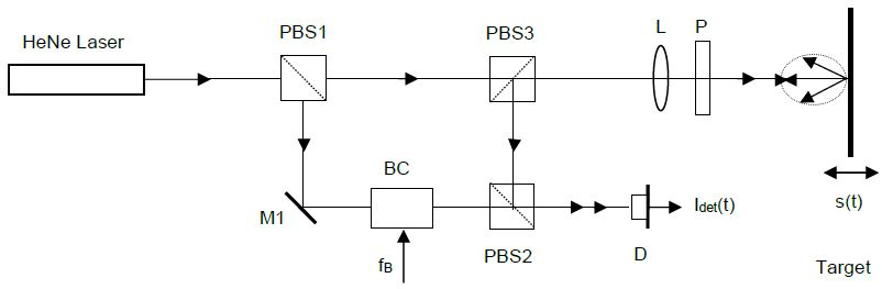
Figure 1. Optics schematic of a modified Mach-Zehnder Interferometer. Image Credit: Polytec
The signal which is measured at the photo detector carries direction sensitive frequency as well as phase modulation from the moving target.
Target displacement s(t) results in a phase modulation
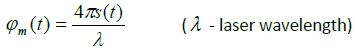 |
(1) |
According to the basic relationships dφ/ dt = 2πf and ds / dt = v, that phase modulation corresponds to a frequency deviation
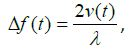 |
(2) |
which is then known as the Doppler frequency. The resulting frequency of the detector output signal precisely preserves the directional information (sign) of the velocity vector.
The measurements that LDV takes are dynamic by nature, and unlike alternative techniques like digital holography or white-light interferometry, do not transport any information about static shape. Velocity and displacement are encoded in phase and frequency modulation of the detector output signal. Phase and/or frequency demodulation techniques are used in the signal decoder blocks of a laser vibrometer to recover the displacement and velocity time histories from the modulated detector signal.
Direct conversion of the instantaneous Doppler frequency into voltage proportional to vibration velocity is possible with both digital and analog frequency demodulators.
Critical accuracy, linearity, sensitivity and signal-to-noise ratio for complete vibrometer system are provided by the high-quality demodulation electronics used.
The LDV measurement instruments can be extended to a 3D vibrometer setup, which therefore enables pm-resolution for both in-plane motion and out-of-plane motion. The optical setup is based on heterodyne Mach-Zehnder interferometry, which has three linearly independent interferometer paths (see Figure 2).
The laser beam which is directed on-axis through the main interferometer is frequency-shifted acousto-optically, with respect to the three reference beams by a Bragg-cell. Subsequently, the scattered light is collected both on-axis and in two off-axis directions. The three detector signals possess the complete broad-bandwidth 3D vibration spectra, at the measurement spot. Here, to derive the vibration data in Cartesian coordinates, coordinate transformation is employed.
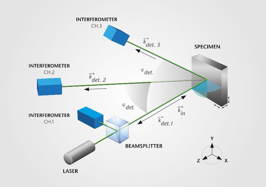
Figure 2. Optical layout of 3D laser vibrometer. Image Credit: Polytec
Instead of being captured on a full field as occurs with video interferometry techniques, standard LDV measurements are at a single point. The LDV technique is extended to full area scanning by deflecting the laser measurement beam in x and y direction using scanning mirrors. Figure 3, below, depicts the schematic for this with scanning mirror M. On the live microscope video, the laser measurement beam can be positioned to any point that is visible.
To measure the velocity field of the structure, this technique is used to scan an area point by point. Despite the fact that a single point LDV can be considered in a similar way to a conventional sensor (i.e. analog output recorded by oscilloscope or other data acquisition systems), system software is required by the scanning LDV in order to generate a scan measurement grid, to keep control of the scanning process and same-time acquisition of the measurement data.
Each point’s phase is established by the simultaneous measurement of an additional reference channel (usually, this is the drive signal that is produced by the internal signal generator). 3D deflection shapes are calculated from this data. The result thereof consists of the mapping of the velocity and / or displacement field over the structure which allows 3D animations of the response, either in the time or frequency domain (see figures 12, 14, 15 and 16).
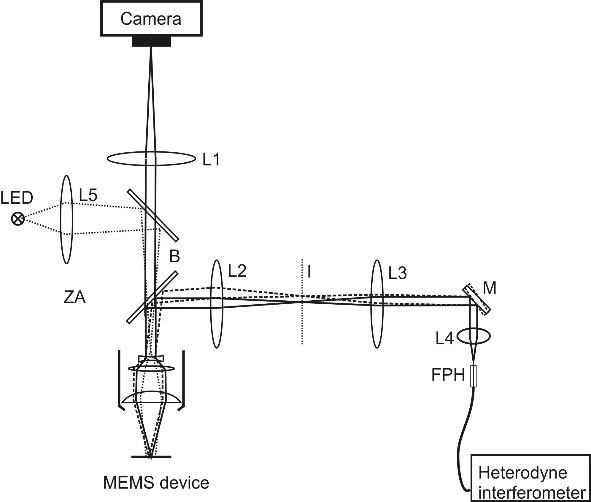
Figure 3. Optical layout of microscope scanning laser vibrometer. Image Credit: Polytec

This information has been sourced, reviewed and adapted from materials provided by Polytec.
For more information on this source, please visit Polytec.