In the last few years, utilizing near-infrared (NIR) wavelengths for three-dimensional (3D) sensing has grown in applications such as iris, facial, and gesture recognition, eye tracking, and automotive vision systems such as LiDAR.
In the coming years, the market for these optical sensing systems is estimated to have a 22.7%1 to 24%2 compound annual growth rate (CAGR), and by 2027, reaching as high as $3.8 billion in industry revenues.1
Infrared light waves are invisible to the human eye, with “near-infrared” wavelengths ranging from around 700 nanometers (nm) to approximately 2,500-3,000 nm. NIR and infrared wavelengths are commonly generated by lasers and LEDs (light-emitting diodes).
Laser NIR wavelengths are commonly produced by Vertical-Cavity Surface-Emitting Lasers (VCSELs) for applications like facial recognition, automotive LiDAR, fiber-optics (telecommunication), and gesture recognition. Usually, NIR facial recognition systems use 850 or 940 nm wavelength light.
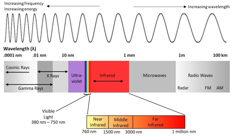
Figure 1. A representation of the electromagnetic spectrum, including the range of light visible to humans at wavelengths of approximately 380 - 750 nm, and near-infrared light at wavelengths of approximately 700 - 3000 nm.3
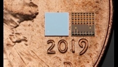
Figure 2. Front and back images of a mobile NIR VCSEL chip, on a penny for scale. (Image: Copyright TriLumina Corporation, used by permission)
For proximity-sensing and autofocus applications, NIR lasers supply better accuracy than LEDs. This is because lasers may be directed more precisely and reflected for hand gesture and facial recognition.
Due to their spatial coherence and focus, laser beams can pass through small-diameter openings, making it simple to manipulate and integrate through diffractive elements.
Laser NIR permits 3D imaging solutions with superior mapping capabilities and depth measurement, by using structured light (projecting light in a known pattern), for example, for applications such as facial identification.
This article outlines how NIR light can be employed for 3D facial recognition systems, and the techniques for measuring and testing NIR emitters to help make sure that they are effective and accurate for employment in consumer electronics applications.
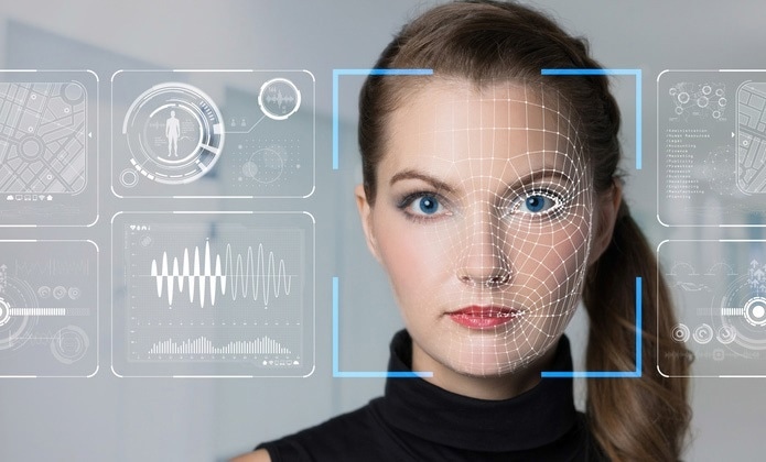
Figure 3. NIR facial recognition systems work by projecting a pattern of dots onto a person’s face. By reading how the dot pattern is reflected back, the system creates a 3D “map”, which can be matched to a stored image to verify a user’s identity
Flood Illuminators / Time of Flight
One use of NIR LEDs in facial recognition systems is to determine the distance and/or presence of a user’s face in darkness or daylight. The device emits a flash of NIR light (flood), and an NIR sensor receives signals which are reflected from the object.
By calculating “time of flight” (TOF), the distance of the user’s face is established, calculating the time it takes from the NIR flood emission to the return of the light’s reflection back to the device sensor.
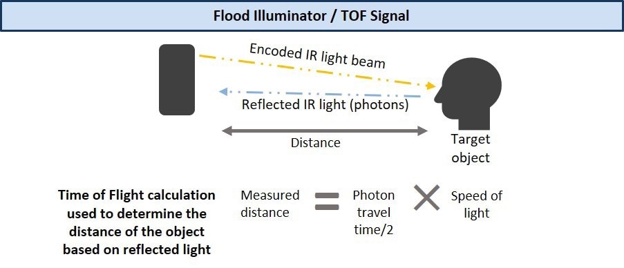
Figure 4. Some devices include a camera with a pulsed NIR light source, which will only accept reflected NIR light with the correct pulse. The return pulse is used for TOF.
Diffractive Optical Elements (DOE)
When structured light is utilized for NIR sensing, a single beam from an NIR laser is projected through an optical structure (a diffractive optical element, or DOE) to split the laser into several emission points and cast minuscule invisible dots in a fixed pattern or grid onto a 3D object (like a person’s face).
An infrared camera measures how the pattern has been deformed when the light from each dot is reflected from the object, and translates the reflected light using processing software to establish the contours of the object. Facial recognition systems can possess more than 30,000 individual dots.
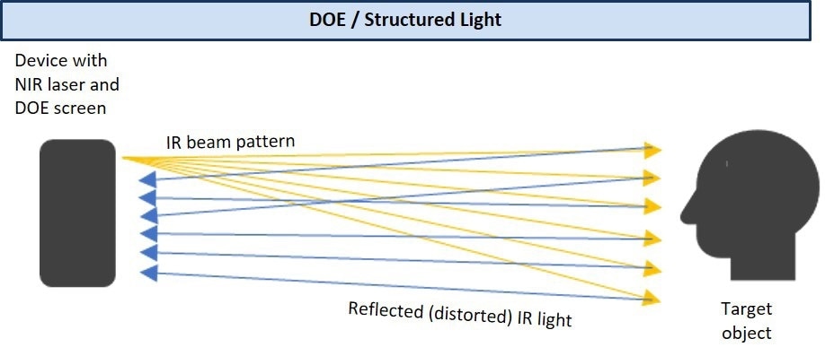
Figure 5. For facial recognition, AI algorithms read the reflected pattern and infer depth and positioning of the object features, to construct a 3D “map” of the face, which is compared to known parameters (such as a stored image) to authenticate the user.
NIR sensors can receive NIR reflections from a user’s face accurately to interpret the 3D features unique to each individual, as they are not affected by visible light. For identification, this NIR facial “map” is matched to a stored image.
NIR facial sensing ensures that only the user can access their personal information, car, bank account, or other protected media. They cannot be hacked with a 2D photograph, because NIR systems sense depth, supplying enhanced biometric security.
NIR facial sensing can also be utilized to identify individuals for crime prevention, permitting law enforcement to spot target individuals, even among a crowd.
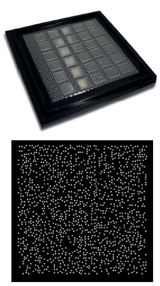
Figure 6. A diffractive optical element (top) and a sample random dot pattern (bottom) created by projecting laser light through a DOE. (Images: Copyright Holoeye Photonics AG, Germany, used with permission)
Quality Considerations for NIR Sensing Systems
The fast adoption of 3D NIR sensing systems comes with increased demand for effective techniques to measure the accuracy of NIR emitters. While 3D NIR technology supplies more accurate facial recognition than previous 2D (photographic) techniques, NIR systems can still have performance issues.
What happens when low-output or poorly placed emissions are interpreted by the sensing device or the NIR emissions are inaccurate in scope or intensity?
Safety Considerations for NIR Sensing Systems
When working with NIR wavelengths there are some safety considerations. They do not trigger an “aversion response” (blinking or looking away from bright light), as they are invisible to humans.
However, NIR wavelengths can enter the eye and, with too much power (too much irradiation per area) or extended exposure, they can damage the cornea or retina.
Eye and facial recognition systems that emit light in the NIR range must be carefully designed and tested for safety reasons to make sure that they are emitting at correct levels. For device accuracy, quality, and performance, manufacturers use measurement techniques to test the design and manufacture of NIR sources.
Ideally, a measurement system captures a range of different characteristics like maximum power or intensity, emission uniformity, emission distribution radiant flux, or spatial position – and it measures these parameters over the whole distribution area.
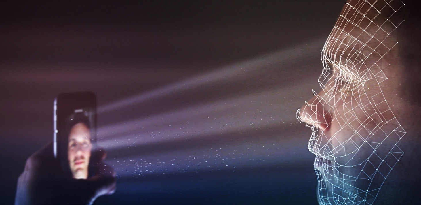
Figure 7. Visual representation of an NIR system being used for facial recognition. The device emits a DOE dot pattern (invisible to the user) that is cast on the face and can shine into the eyes.
Challenges of Testing NIR Emitters
Facial recognition systems present multiple challenges for NIR performance evaluation. Capturing NIR light in angular space is extremely difficult for traditional measurement equipment, particularly when identifying up to 30,000 emission points generated by today’s smart device DOEs.
The utilization of image-based NIR measurement systems (for example, a radiometric camera) for NIR source measurement can limit this complexity by capturing and quantifying all emission points generated by a DOE over a large spatial area.
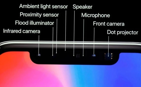
Figure 8. Configuration of the Apple® iPhone® X with facial recognition (including infrared camera, NIR flood illuminator, and NIR dot projector) as announced on Sept. 12, 2017. (Image: AP Photo/Marcio Jose Sanchez)
The testing device must capture and evaluate a large angular distribution quickly and at close range in order to analyze the entire emission area that will cover a face. To accomplish this, a wide-angle scope is necessary, since the NIR-emitting device is usually located at a short distance (such as a smart phone held in a user’s hand).
Like any light source, an NIR light emits light in 3D angular space. Each dot in a DOE pattern may vary in position or intensity based on emission angle.
To ensure that dot patterns are accurately projected and that each dot has enough intensity to be received and correctly interpreted by the device’s NIR sensor, quantification of the NIR dot pattern must be carried out at each emission angle.
Traditional Angular Measurement
Usually, a measurement system known as a goniometer is used to rotate an NIR light source in front of a photodetector or a camera to capture 2D images of emissions. This is done to assess radiant intensity at each angle (measured in watts per steradian, W/sr).
This process is time-consuming and requires thousands of rotations to capture a complete angular measurement. Gaps in measurement can also happen between goniometric rotations, missing irregularities in NIR intensity at particular points.
All angular distribution points of an NIR source must be measured, as NIR emissions can be dangerous to human vision. Missing any point during measurement may mean missing an emission that is irregularly strong and could be hazardous to the user, especially over time.
New Angular Measurement Solution
Used as an alternative to goniometers, a camera combined with Fourier optics prevents the requirement for device rotation by capturing angular emission data directly from a single point.
Lenses designed using Fourier optics principles allow connected imagers to quantify the full angular distribution of a light source, leaving no gaps in measurement.
Advanced NIR measurement systems utilize Fourier optics to gather a full cone of data in a single image, in order to measure radiant intensity of a complete NIR light source. Identifying peak emission, irregularities, hot spots, and other issues across angular space (Figure 9).
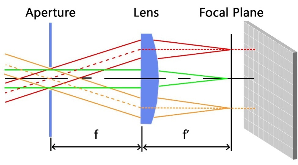
Figure 9. Illustration of Fourier optics directing angular emissions of light through the specialized lens onto points on an imaging system’s sensor, forming a 2D polar plot of the 3D distribution.2
DOE Dot Pattern Measurement Challenges
It is crucial to examine every single dot for accuracy when evaluating NIR DOE emissions for facial recognition. Until now, the technique for measuring DOE emissions was limited to checking dot patterns for accuracy by mapping them against coordinates or target patterns (usually with the source cast against a screen or wall).
Yet, this technique does not dynamically adapt to new DOE patterns nor can it report precise radiometric data of the DOE emission points (like radiant intensity, size, power), supplying only dimensional evaluation (like location).
Every dot in a facial recognition DOE array has to be positioned accurately (inclination, angle, azimuth) and emitted with the correct radiant intensity (W/sr) to make sure that it is reflected back correctly and “understood” by the device’s infrared sensor.
Manufacturers must control the output and position of each dot for the device to map facial contours accurately.
The ideal measurement system should identify points of interest across the image, measure values for each dot in the pattern, and assess the accuracy of the pattern to achieve thorough evaluation of dot-by-dot performance and accuracy.
Traditional Dot Pattern Measurement
A traditional measurement method which is used for DOE-generated patterns is to cast the dot pattern on a screen or wall and then measure the reflection of the dots using an imaging system.
This approach is employed to verify dot position against defined coordinates, or a target pattern, providing a simple pass/fail evaluation based on pattern match. With this technique, intensity of the dot emissions cannot be measured effectively.
Other limitations include the requirement for a relatively large projection screen taking up a lot of space, a limited field of view, and that the image resolution can be decreased because of diffusion by the screen material.
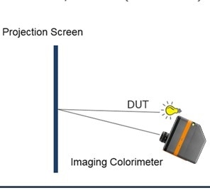
Figure 10. Wall/screen measurement method.
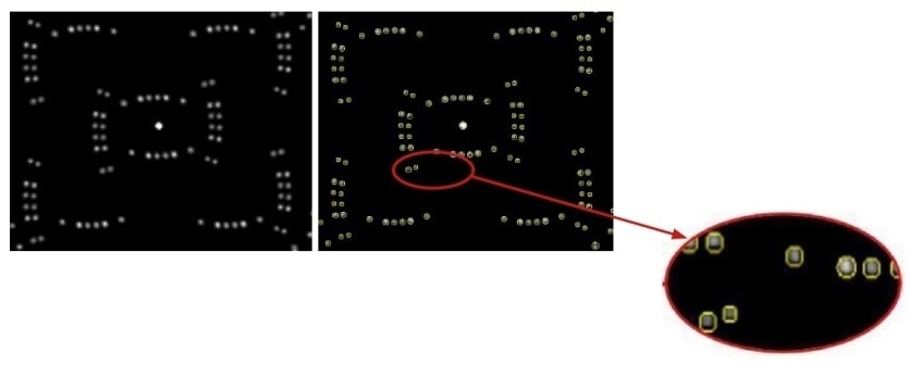
Figure 11. (Left) Sample portion of a dot pattern before (left) and after analysis (right) using automatic dot detection in Radiant’s TT-NIRITM software module.
Figure 12. (Right) Close up of dots in TT-NIRITM software, which measures maximum peak (strongest emitter), maximum peak location (inclination/azimuth), maximum peak averages, maximum peak solid angle, number of pixels as maximum peak point, spot power uniformity (between dots), total flux, and DOE flux, along with dot-by-dot measurements.
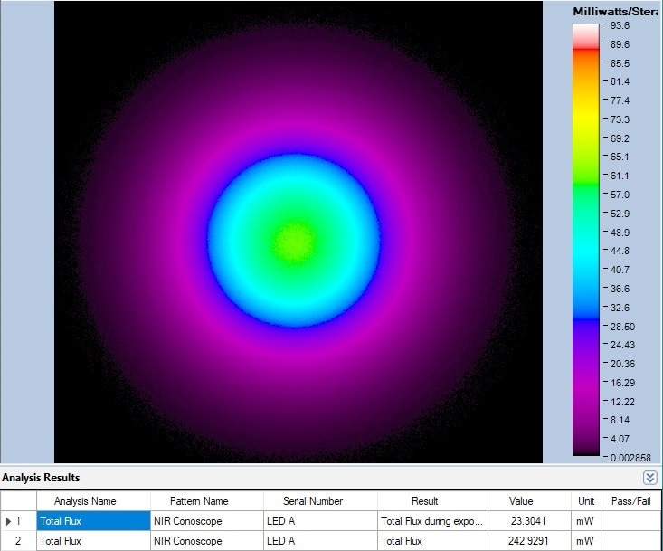
Figure 13. Example of a Total Flux analysis of an NIR LED over angular space, shown in a false-color scale in Radiant Vision System’s TT-NIRI software. Radiant flux is a measure of radiant energy emitted per unit of time, e.g., Watts (joules per second).
Radiant NIR Measurement Solution
The Radiant Vision Systems Near-Infrared (NIR) Intensity Lens system is an integrated camera/lens solution which quantifies the radiant intensity and angular distribution of 850 or 940 nm NIR emitters.
The system utilizes Fourier optics to gather a full cone of data in one measurement to ±70 degrees inclination and 360 degrees in azimuth, providing quick, accurate results, which are ideal for in-line quality control.
Manufacturers of 3D sensing technology can use the NIR Intensity Lens solution for angular measurement of lasers, NIR LEDs, and structured light patterns generated by Diffractive Optical Elements (DOE).
The lens features ProMetric or TrueTest™ Software for intuitive system setup and customizable automated measurement sequences and is integrated with a Radiant Vision Systems ProMetric® Y16 Imaging Radiometer. Further tests which are specific to NIR emission measurement are also included in the TT-NIRITM software module.
Flood Measurement Considerations
As outlined above, some facial recognition systems depend on a “flood” function, which is a strong flash of NIR light utilized to detect a user’s face and establish focus distance.
As with all NIR emissions, this flood function must also be tested to ensure it adheres to defined performance parameters. Irregularities like hot spots or a fall-off of intensity around the perimeter must be identified and corrected.
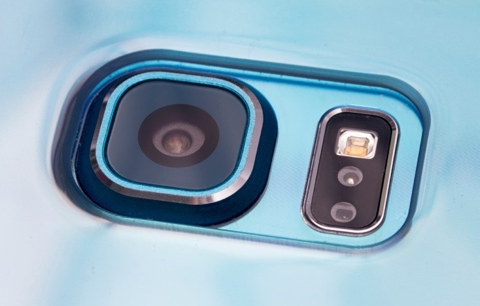
Figure 14. Close up of the flood illumination source on a smart phone.
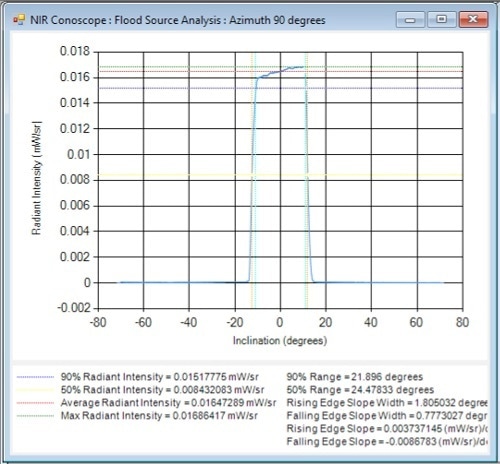
Figure 15. Flood source emission cross-section derived from TT-NIRI analysis software.
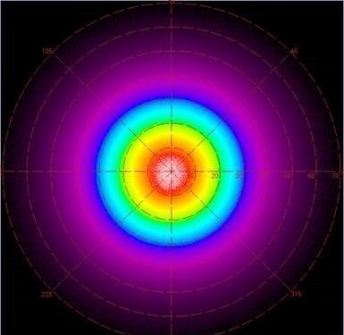
Figure 16. The angular distribution of an NIR flood projector, as captured in a single image by the NIR Intensity Lens and shown in false color (heat map) polar plot generated in TT-NIRI analysis software.
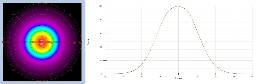
Figure 17. Radar plot and cross-section showing radiant intensity (as function of angle) of a near-infrared LED. Captured by a Radiant Vision Systems NIR Intensity Lens and shown in the TT-NIRI software platform for light source measurement. The Fourier-optic lens is calibrated to its connected imaging system, allowing it to accurately map angular emissions of the NIR device to +/- 70° at once.
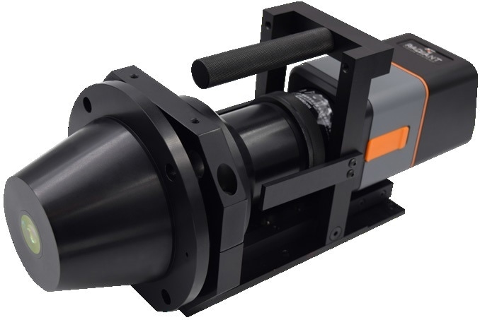
Figure 18. Radiant’s NIR Intensity Lens solution measures NIR laser and LED emissions.

Figure 19. Radiant Vision System’s TT-NIRI™ software module includes pre-defined tests to evaluate near-IR emitters for angular distribution, radiant intensity, uniformity, hot spots, fall-off, and statistics on structured light (e.g., DOE dot patterns).
Test Suite for NIR Intensity Lens System
Part of the Radiant Vision Systems TrueTest™ Software family, the TT-NIRI™ software module supplies the advantages of TrueTest Software to perform image-based measurements efficiently, but with application-specific tests to assess the accuracy of 850 or 940 nm NIR LEDs, structured light patterns, and lasers.
TT-NIRI assesses all angular emissions of a source in a single image using the Fourier optics of the NIR Intensity Lens solution, in addition to all dots in a structured light pattern produced by diffractive optical elements (or DOE).
A Radiant NIR test solution gathers and processes data more consistently and a lot quicker than a goniometric or spot measurement device.
DOE dot source analytics gathered by the NIR Intensity Lens and TT-NIRI software provide comprehensive radiometric data, which cannot be collected with alternative techniques like casting a dot pattern against a wall or other Lambertian surface.
DOE Dot Source Analysis
Evaluating the accuracy of NIR emissions relies on radiometric measurements to establish the intensity and scope of NIR-emitting sources, plus the angular location of precise emission points (dots) against defined tolerances.
To ensure that patterns are projected at the correct angle (inclination, azimuth) and intensity (W/sr), the Dot Source Analysis test can measure every dot in a DOE pattern.
TT-NIRI supplies a comprehensive NIR test suite which enables users to establish measurement parameters and pass/fail criteria for certain points of interest in an image. Data output for each dot can include a full set of data measured for every point.
Some DOE patterns contain over 30,000 dots, and TT-NIRI supplies data for each dot in the pattern, including flux, intensity, peak, location, and more.
Conclusion
A new generation of devices that utilize NIR emitters for 3D sensing demand new methods for product quality testing to ensure the accuracy and performance of these invisible light sources.
Applications such as facial recognition, eye tracking, and automotive LiDAR which are utilized on and around humans need intensive testing to comply with industry and internal standards.
Radiant’s near-IR measurement solutions quantify the output of NIR sources, supplying manufacturers with data that could be useful when testing to these standards. Advancements in NIR testing using radiometric measurement systems and specialized Fourier optics have been crucial.
The Radiant’s NIR Intensity Lens solution provides the benefits of size, speed, and software for precise measurement of 3D facial recognition systems, carried out more efficiently than traditional techniques such as goniometric solutions, and with minimal equipment.
Sources and Further Reading

This information has been sourced, reviewed and adapted from materials provided by Konica Minolta Sensing Americas.
For more information on this source, please visit Konica Minolta Sensing Americas.