Traditional optical microscopy is generally tied down to a sample magnification of around 1000x, this is due to the wavelength range of visible light (400—700 nm). Optically resolving two particular points on a sample can be completed using a standard microscope – as long as they are no closer than ~0.2 micrometers (μm) to one another.
While ground-breaking in its own time, the compound microscope now lags behind alternative modernized tools possessing the ability to perform high-precision material characterization or insights into molecular activities on the nanoscale.
A multitude of methods and practices have been developed to circumvent the limited resolving power of conventional microscopes. Super-resolution optical microscopy, scanning, atomic force microscopy (AFM), electron microscopy (SEM) and many more have become known as more than sufficient candidates for surface metrology. All of these techniques are reliant on some motion – in the case of SEM, an electronic beam can be deflected without using mechanical components. However, in the case of AFM and super-resolution optical microscopy, mechanisms capable of achieving great accuracies are needed to move the probe or sample.
Outlining Piezo-Based Nano-Positioning Equipment
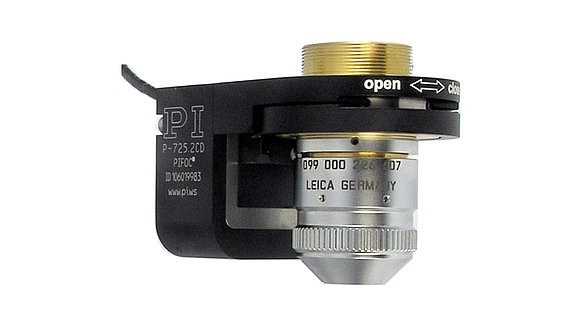
P-725 Piezo Z-Scanner for Microscope Objectives
Piezo mechanics are regularly put into service because they offer unlimited resolution and rapid response. To align, adjust, or scan the position of samples with sub-atomic resolution, Piezo Nano-positioning stages are used as they offer the ultra-precise positioning for micro- and nanoscopic imaging. Piezo mechanisms can also respond at high-speed to a control signal in less than one millisecond. These are properties that have proven instrumental for fast-focusing and 3D imaging applications.
Piezo-based positioning equipment can incorporated into research and OEM equipment with the greatest of ease for testing that is dependable at industrial-scale speeds. Driven by piezo transducers, most Nano-positioning stages are flexure-guided (friction-, maintenance-, and wear-free).
These ceramic actuators are well-equipped to enable the conversion of an electric charge into rapid linear motion and force with virtually unlimited resolution. Even micro-changes in operating voltage are subsequentially converted into controlled movements which allow for extremely accurate positional adjustments down to the sub-nanometer range. In addition to piezo-flexure Nano-positioners that provide a motion range of typically 100 µm to 1 mm, other types of piezo motors are offered for longer travel microscope stages. Here, the robust piezo motors provide great stability due to their self-locking nature, once a position has been reached.
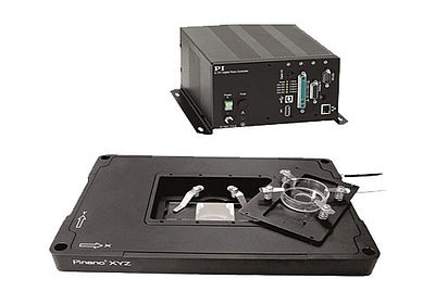
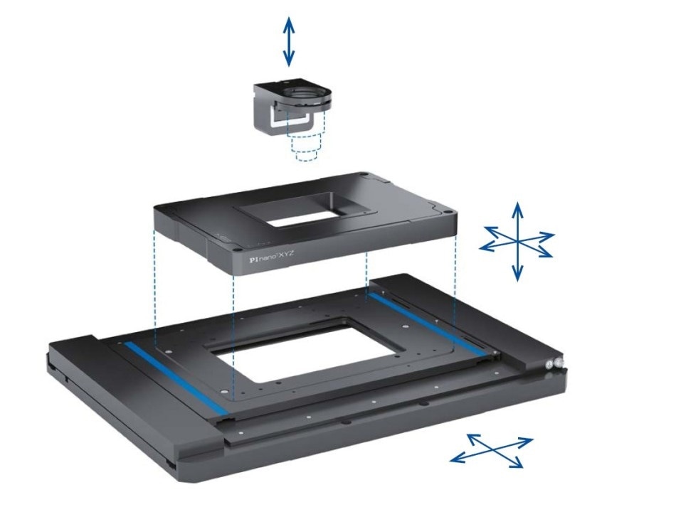
P-545 XYZ Piezo Nano positioning Stage with Advanced Controller for Super-Resolution Microscopy
As well as their unparalleled precision, piezo-based positioning equipment comes with great reliability and can also be engineered into very compact, low-profile motion systems.
Nano-Positioning Equipment from PI
PI provides a wide scope of positioning equipment sufficient for sub-nanometer resolution microscopy and interferometry. PI XY and XYZ piezo flexure scanners are engineered and designed to mount on both manual or motorized microscope stages with simple housings or additional inserts and slides. PI piezo Z-scanners typically outmaneuver alternative motorized positioning equipment, reaching accuracies up to 10x greater with enhanced focusing speeds. These include:
- P-725 PIFOC Objective Scanner: With a response time of milliseconds and 400 µm of vertical travel, the Z-scanner is perfect for high throughput microscopy, biotechnology screening, and testing applications.
- P-736 Piezo-Z Sample Scanner: With a range of vertical motion up to 220 μm and a resolution of a single nanometer, this low-profile Z-scanner is offered for both microscopic slides and multiple well-plates for microbiology and life sciences studies.
Learn more about PI’s precision positioning equipment for microscopy applications, and read their blog-post Advanced in Precision Motorized Positioning Systems: Selection Criteria. .

This information has been sourced, reviewed and adapted from materials provided by PI (Physik Instrumente) LP.
For more information on this source, please visit PI (Physik Instrumente) LP.