
Super-Resolution microscopy is a particularly useful approach that allows for enhanced observations into intracellular interactions and processes at a molecular level. Over the past twenty years, significant advances in the field have led to the obtaining of images at a much higher resolution, swift processing times, and insight into the functionality of molecular machines within cells. We explore how nanometer precision, positioning and measuring technology has given a much-needed boost and opened the door to rapid progression in this field, and the importance of nanopositioning for Super-Resolution microscopy applications.
Background
Through further development of super-resolution microscopy (SRM) renewed interest in the use of optical microscopy has been generated across a good number of life sciences research, notably molecular cell biology and neuroscience. This method, first proposed back in 1978, overcomes the so-called Abbe diffraction limit – posited by German physicist Ernst Abbe over 100 years prior in 1873 – permitting structures of less than 200 nanometers to be detected with fluorescence-based light microscopy.
Super-Resolution microscopy did not really get the recognition it warranted until about 15 to 20 years ago, when researchers began merging a number of separate super-resolution technologies, including 4Pi, light sheet, PALM (photoactivation localization microscopy), STED (stimulated emission depletion), and STORM (stochastic optical reconstruction microscopy) – to produce modernized systems that could achieve spatial resolutions down to around 20 nanometers. This development garnered much praise and eventually led to Eric Betzig, Stefan W. Hell, and William E. Moerner being awarded the 2014 Nobel Prize in Chemistry. What’s more is that this advanced technique has greatly expanded the understanding of many intracellular processes and molecular interactions.
Since commercially available super-resolution systems became accessible, SRM techniques now allow cell biologists to non-destructively investigate cellular structures in previously unattainable detail, with its use growing at a rapid rate.
While there are many benefits to using these optical microscopy systems, one noticeable advantage is that unlike alternative methods that offer comparable resolution – such as scanning electron microscopy (SEM) – SRM techniques can be used to investigate metabolic interactions in living cells. The increased popularity of SRM has therefore encouraged a large number of laboratories to reconsider and revise their imaging-based research in areas such as intracellular transport and cell division. These research areas were being held back by diffraction-limited image resolution – new methodologies were made better by combining selective labeling with the ability to distinguish co-localized molecules of interest using spectrally separated fluorescent dyes.
Comparable with other new research tools, the progress and primary driver of SRM technologies has been academia with a large number of the systems being used today having their genesis directly from research labs or via university spin-off companies. Due to necessity, the first generation of these instruments was built in-house by physicists by promoting standard parts from other microscope platforms.
Improvement in resolution achieved by SRM techniques was ten-fold and the capability to position samples and objectives with precision was identified as a key requirement to create such systems. Fortunately, piezo-based positioning systems – with nanometer resolution – were commercially available during the first phase of SRM development. Furthermore, they were widely used in other high-resolution imaging techniques such as SEM and atomic force microscopy (AFM). Consequently, piezo-based nanopositioners became a key contributor to the development of SRM techniques.
The Piezo Effect
The discovery of Piezo technology was discovered in 1880 by brothers Jacques and Pierre Curie. Deriving from the Greek word piezein, which means to squeeze or press the Curie brothers identified that applying pressure to crystals such as tourmaline and quartz, produced an electrical charge.
This effect represents the conversion of mechanical energy into electrical energy – known as the ‘direct piezoelectric effect’ – in crystals and ceramics with non-symmetric elementary cells below the Curie temperature. Later, the brothers went on to discover that inverting the process and thus applying an electric field to certain crystals can deform the material, resulting in a change of its length – the inverse piezoelectric effect.
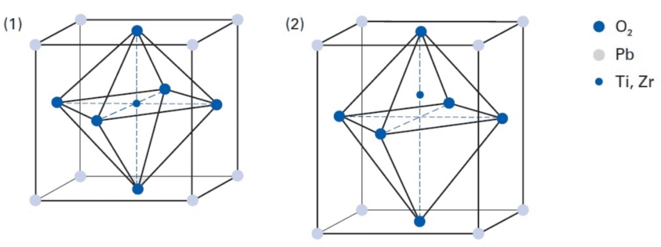
Perovskite crystal structure of PZT (1) Structure above Curie temperature, with Ti or Zr in non-piezoelectric, symmetrical cubic structure. (2) Structure below Curie temperature, showing the non-symmetrical tetragonal structure which allows piezoelectric conversion (Image: PI Ceramic)
The piezoelectric effects in natural monocrystalline materials, such as quartz and tourmaline, are comparatively small. Yet, by engineering polycrystalline ferroelectric ceramics, including barium titanate (BaTiO3) and lead zirconate titanate (PZT), much larger displacements occur, or larger electric voltages are induced. Doping these piezoceramic materials with ions can also be effective – for example Bi, La, Nb, Nd, or Ni, – to make best use of the piezoelectric effects and parameters, thus, this optimization allows each piezo component to be individually adapted according to the intended application.
Practical Applications
Long considered the gold standard, piezoelectric actuators allow for positioning with greater accuracy of both sample stages and objectives in a wide range of microscopy techniques. This technology is majorly beneficial because movement is controlled by precisely converting electrical energy into mechanical motion through solid-state effects. Theoretically, the piezoceramic material itself has limitless resolution, enabling accurate, stable, and reproducible fine placement right down to the sub-nanometer range, and travel ranges between ten and a few hundred micrometers for microscopy-related applications, including sample stages and Z-focusing drives, as standard.
Many of these products have been in widespread use for over 20 years in spite of this level of precision being deemed unnecessary for conventional light microscopes. However, due to their combination of high-speed movement, positional accuracy, and improved stability compared to motorized drives, these products are considerably advantageous.
Piezo-based nano-focus drive. Typical travel ranges are 100 to 500 µm, special piezo-motor or voice-coil-driven units with 2-15 mm travel are also available. Learn more
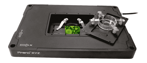
PInano XYZ piezo flexure slide nanopositioning and scanning stage, 200 µm travel, 1 nm resolution. Learn more
With no moving mechanical parts typically found in piezo materials, the resulting motion is friction-free and not subject to wear, in effect making them maintenance-free and capable of several billion cycles without presenting measurable changes in their behavior. They are also both clean room and vacuum compatible.
Another favorable attribute of piezo ceramic material is its extremely fast response to a drive voltage change combined with acceleration rates of thousands of g’s. Piezo-flexure-driven nanopositioning stages with travel ranges in the 100 µm to 500 µm range achieve step and settle times from 5 to 20 milliseconds, in real-world scenarios, while long travel stages with ultrasonic piezo motors can achieve velocities up to hundreds of millimeters per second, making them a sound choice for high throughput and fast scanning microscopy applications.

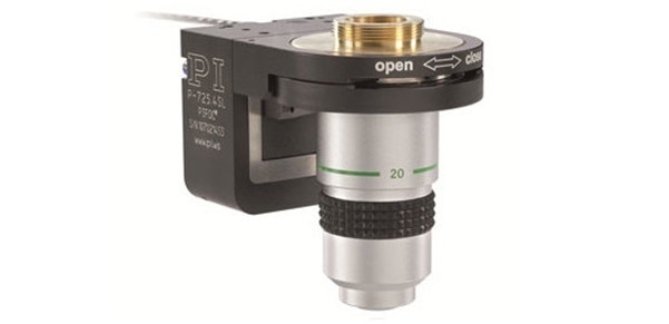
Rapid response: The P-726 Piezo Focus Drive can step and settle is less than 6 thousands of a second Learn more
Alternatively, the implementation of piezoceramics in standing and traveling wave ultrasonic motors for microscopy stages with travel ranges of 100 mm and above, or rotation stages with unlimited rotation, is possible. These motors give a dynamic velocity range that is wide in scope – from less than one micron per second to hundreds of mm per second.
With a proven track record that spans multiple microscopy disciplines, piezo actuators and motors are the natural choices for laboratories developing the first generation of SRM platforms. They offered familiarity to researchers and known performance levels that met requirements.
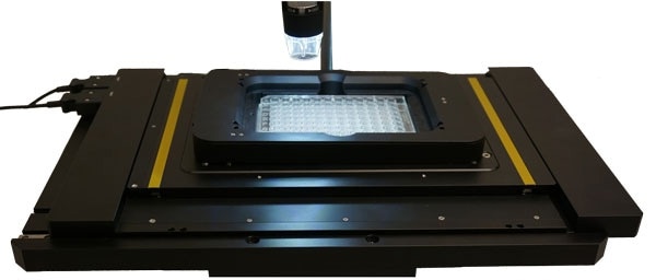
A piezo-Z-stage insert with well plate on a long travel XY microscope stage based on ultrasonic piezo linear motors. Compact design, a wide dynamic range from less than 1 µm/sec to 100 mm/sec, and rapid response are benefits of the stiff piezo motor design. High positional stability is achieved due to the self-clamping nature of these direct-drive motors. Learn more
Nanometers Ahead
It may appear serendipitous that these ceramic actuators were already in commercial use and offered resolution almost two orders of magnitude higher than was typically required for existing light microscopy processes, but the additional qualities of this technology – excellent reproducibility, exceptional stiffness, and extremely rapid movement – made it a rational choice. The emergence of SRM has now enabled optical microscopy to utilize the capabilities of these existing electro-ceramic elements to their full potential.
For the success of high-resolution microscopy techniques, they must be able to generate precise and reproducible positioning of imaging elements or samples. Applications range from detailed Z-focus placement of light microscope objectives in the depths of field to high-precision positioning of tiny biological samples for 4Pi Resolft 2-Photon super-resolution fluorescence microscopy. Also, in AFM, SEM, and TEM, as well as correlative microscopy, adaptable nanopositioning solutions provide unparalleled assistance to even the most complex of positioning tasks.
Presently, piezo mechanisms are deployed across three main applications in SRM: sample positioning; Z-positioning of objectives for autofocusing; and for manipulation of illumination systems (such as in light sheet and 4Pi techniques). Each of these processes has specific requirements in terms of reproducibility, range of travel, and settling times but, in broader terms, system integrators want piezo-controlled movements to be as accurate, fast, and stable as possible.
Why Speed Matters
Due to the resolutions which can be achieved using SRM being outstanding, the result is a decrease in the field of view. Therefore, there is a notable increase in the number of images required to complete a full scan of even a single plane of an individual cell. For other methods that offer a similar image resolution, for example SEM, any proliferation of the number of images required, and subsequently the time taken per scan, is not a cause for concern, as they can only be used with inanimate materials or dead cells which will not change during the course of the scan.
In contrast, SRM enables the continuation of metabolic processes throughout image acquisition. The piezo actuators uniquely influence the quality of experimental results as the faster a scan can be completed, the better it is representative of a ‘snapshot’ of a single time point. This, in addition to the potentiality of scanning through the entire Z stack to create a 3D render of a cell or tissue and any improvements that can speed up imaging – reduced drift, longer travel for sample stage movement, shorter settling times, etc. – become vital.
Finding Your Molecule Again
When quantitative image analysis is underway, it is of great importance that users can bookmark the position of cells or structures of interest then relocate those same structures later or on a different instrument with speed and consistency. This is particularly significant for longitudinal (time-lapse) studies to understand molecular, metabolic, and information transport on a cellular level, as these processes tend to have limited timescales.
Furthermore, there is also increased importance on Bidirectional positioning reproducibility – the precision with which the system can return to a specific X and Y position. Furthermore, piezo-nanopositioners can be depended on to move the sample or objective to the correct place with great accuracy at a consistent rate. By enabling the motion of the stage to be calculated with a capacitive sensor – without any influence from the drive or guide elements – ensures excellent stability and stiffness, optimum repeatability, and fast-responding control.
Total internal reflection fluorescence microscopy (TIRFM) is a relatively easy and cost-effective super-resolution fluorescence microscopy technique that has been used for many years, and TIRFM systems – such as the GATTAscope – gain advantage from piezo-based solutions. For this process, a laser beam hits the glass surface of a microscope slide, microplate or Petri dish at a total internal reflection angle to stimulate fluorescence.
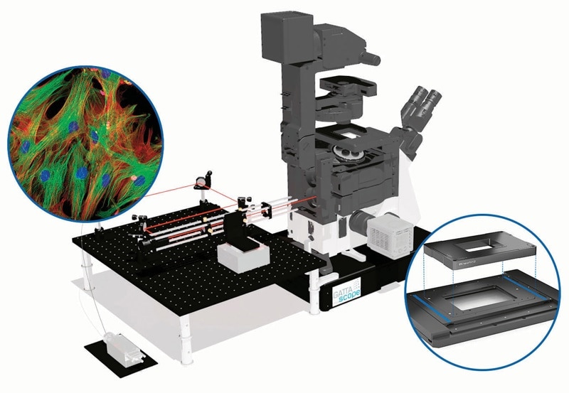
Example of a TIRF microscope – the GATTAscope from GATTAquant. (Image: GATTAquant)
The stimulated area in the Z-plane is reduced since the electromagnetic field of this beam only infiltrates the sample on the other side of the glass plate to a depth of 100 to 200 nm. This technique clearly offers better Z-resolution than standard wide-field or confocal fluorescence microscopy. Piezo solutions allow for the accurate positioning of the lasers and Z-drive that are vital to successful super-resolution imaging in the Z-direction.
Comparably, light-sheet fluorescence microscopy – as used by the Janelia research group2 – utilizes a distinctive planar illumination approach, orthogonal to the observation direction. This greatly reduces photobleaching and phototoxicity for living specimens, allowing 3D and live-cell imaging of large specimens over a prolonged period.
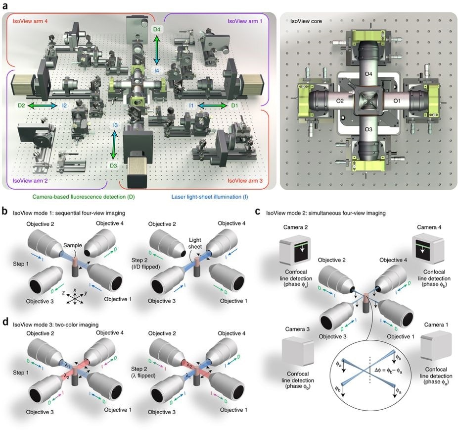
Schematic representation of the IsoView light sheet fluorescence microscope.
Left: (A) four orthogonal arms provide simultaneous light sheet illumination and fluorescence detection. The specimen is located at the center of this arrangement, and volumetric imaging is performed by sweeping light sheets across the sample with objective piezo positioners.
Right: close-up view of sample chamber showing objectives (O1-O4) and piezo positioners.
In mode 1 (B), four views are acquired by alternating light sheet illumination (l) and fluorescence detection (d) along orthogonal axes, with temporal separation used to avoid cross-talk between views.
In mode 2 (C), illumination and detection are performed at the same time in all arms, and cross-talk is avoided via spatially matched beam scanning and confocal detection using a phase offset in orthogonal arms (spatial separation).
In mode 3 (D), different illumination wavelengths are used in orthogonal arms simultaneously, and four views are acquired for both channels by alternating wavelengths (spectral separation).
Observing small organisms in this way means it is necessary for samples to be positioned over a range of a few millimeters in XY with bidirectional repeatability of 100 nm, which can be systematically achieved with ease using piezo-driven stages and objectives.
The nature of piezo-based stages being high throughput permits imaging to be carried out of objects with a large-surface area – i.e. high magnification image recording of objective slides and microwell plates – within seconds. Throughout the recording of an image, piezo-controlled stages continuously move the object with high-precision, either in ‘stop-and-go’ mode or at a constant speed in ‘fly-over’ mode.
Furthermore, it is possible to combine this scanning technique with standard image-processing steps and real-time data handling to ensure that even CPU-intensive tasks such as the superimposed tiling processes run smoothly with little to no delay. Individual images can then be fluently merged into the overall image as acquisition is in progress while continuously adjusting the focus as necessary during scanning.
Summary
Super-resolution microscopy is a significant driving force in our understanding of many cellular processes and molecular interactions. The rapid growth of the field, coupled with the latest generation SRM systems, is leading to spatial resolutions of around 20 nanometers. What’s more, the accuracy of the sub-nanometer positioning offered by current piezo-based drives will assist in further improvements of this resolution.
Despite this, microscope integrators have been long calling for higher speeds, longer travel ranges, and greater stiffness since the production of the very first SRM systems. Thus, the development of customized solutions to meet this ever-expanding demand will be of great importance as optical microscopy drives further into the nano-world.

This information has been sourced, reviewed and adapted from materials provided by PI (Physik Instrumente) LP.
For more information on this source, please visit PI (Physik Instrumente) LP.