"Only the best virtual prototypes are built as physical prototypes. Optical measurements validate their performance."
R&D departments need to rapidly respond to their customers’ requirements and changing markets by optimizing and quickening product development processes. The departments’ success significantly contributes to a company’s competitiveness, and the design process should involve economic thinking and acting. Product development processes involve measurements as well as simulations that are usually performed independently of each other. Usually, various departments with separate budgets perform these tasks. If both measurements and simulations can be made to complement each other by bringing them together, development cycles are speeded up with increased quality and innovativeness of the product.
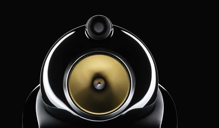
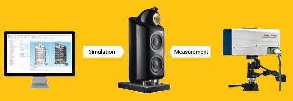
Bowers & Wilkins produces audio systems, and R&D is one of the core processes in the company’s activity. This article shows how Bowers &Wilkins efficiently brings together measurement and simulation to optimize its loudspeaker cabinet design. The company’s R&D department engineers employ COMSOL Multiphysics for simulations, Polytec’s Scanning Laser Doppler Vibrometer (SLDV) for measurements, and combine both in a holistic design process.
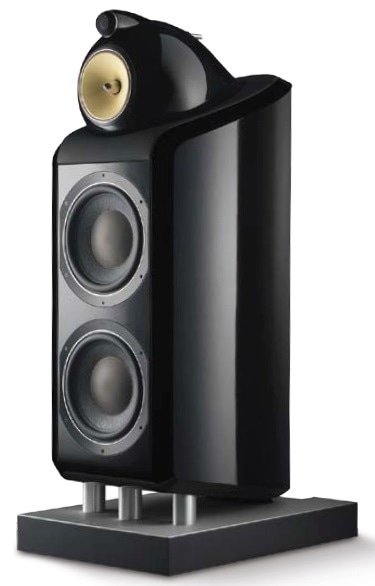
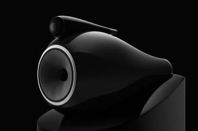
B&W Bowers & Wilkins 800 Diamond
The Challenge of Loudspeaker Cabinet Design
For loudspeaker cabinet design, the cabinet must not contribute to the total sound radiation. There are three ways by which the cabinet can radiate sound, and therefore, they must be avoided or compensated for:
- Sound waves from the backside of the loudspeaker are out of phase with the ones on the front. This results in distortion of the signal due to time lags, echoes, and reverberation.
- The electrodynamic transducer, also referred to as the loudspeaker drive unit, emits sound. The reaction forces of the transducer causes vibration of the cabinet.
- Leakage of sound waves radiated by the cone inside the enclosure through the cabinet walls by transmission
Bowers & Wilkins conducted research to determine the acoustic output of the loudspeaker cabinet by employing finite element simulations to improve the designs (Cobianchi & Rousseau, 2014). A B&W 800 Diamond loudspeaker system was used for the research.
Facing the Challenge
COMSOL Multiphysics was employed by Cobianchi and Rousseau to accurately model the vibration and to compare different design options, and focusing on the low frequency section of the loudspeaker system. The structure-borne sound of the cabinet was measured by using optical scanning laser Doppler vibrometry to validate the simulation results.
The materials employed to assemble the enclosure dictate its quality and performance. Their placements and individual properties affect the acoustic behavior of the loudspeaker cabinet. During the design process, it is important to optimize and test different assemblies and materials in terms of quality and costs. However, it is expensive and time-consuming to build a prototype of a loudspeaker cabinet to measure its performance.
Thus, testing each design option is not possible. Fortunately, a simulation software is perfect for this task since different virtual designs can be implemented and materials can be changed with just a few clicks. Although one cannot only rely on the simulation especially when completely new materials or designs are being considered, it is still the best strategy. This is because, under simulation, only the best virtual prototypes will be built as physical prototypes, and the performance of the prototypes can be validated through measurements or hints can be given at how to further improve the design.
The B&W 800 Diamond used for the research is made of birch plywood for the cabinet wrap, aluminum for the plinth and drive unit chassis, medium-density fiberboard (MDF) panels, neodymium and steel for the loudspeaker motor, and water-based glue joints.
Turning Design Ideas into Simulation Models – Model Setup
Performing simulations involves solving mathematical equations using numerical methods. Sophisticated simulation tools feature intuitive graphical user interfaces (GUIs) in which engineers can select from predefined material properties and suitable domain- and boundary conditions. There is no necessity for the engineers to know, in detail, which equation is being implemented in the background or which numerical method is employed to solve it. From this perspective, it can be stated that almost everyone can perform simulation.
However, the simulation model needs to be efficient in terms of computation time, memory usage and accuracy, and the following questions must be addressed: Can symmetry be exploited in the model? Could it somehow be simplified? Are there areas in the model which are more important than others? If yes, then the model size can be decreased while the areas of interest can be simulated more accurately. In such scenarios, an experienced simulation engineer can help to optimize computation time and model accuracy.
From CAD Design to Model Geometry
The final CAD design is the virtual new product and includes all embellishments, labels, and tiny screws. Many of these do not affect the performance of the product but if they are included in the simulation, then the model size becomes large. The first step in the model setup involves importing the CAD design into the simulation environment. If available, this should be a version of the design without the unnecessary details mentioned above. Additionally, the simulation software also has defeaturing tools to clean up the CAD design.
Communication between COMSOL and many CAD programs is allowed such that design changes are immediately synchronized with the model geometry. Moreover, parameters in the CAD design can be controlled inside the COMSOL GUI to enable automatic access to a number of different design options. Built-in CAD functionality allows to subsequently edit the geometry. The model geometry and the mesh of the loudspeaker in the COMSOL GUI are displayed in Figure 2. For reasons of symmetry, only one half of the loudspeaker is simulated. Cutting and not considering half of the model geometry is built-in CAD functionality.
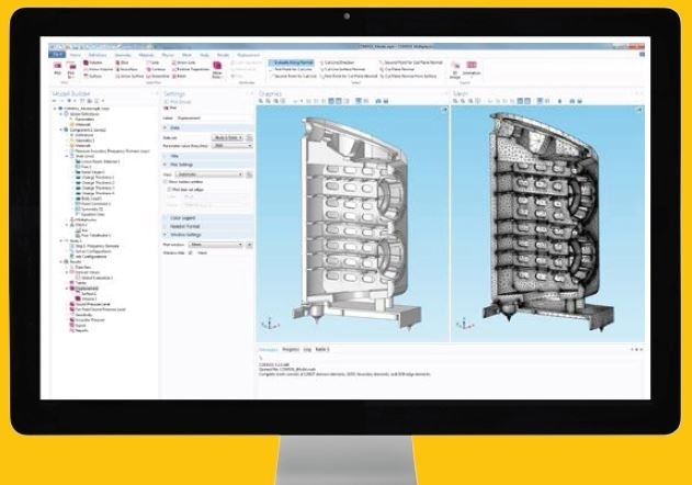
Geometry and mesh of the loudspeaker in the COMSOL GUI
Realistic Simulations Through Realistic Material Properties
Material properties play a vital role in simulation. They are usually anisotropic or temperature-dependent, and may depend on their history. Material properties will change completely if a specific criterion is fulfilled (like phase change or fatigue). They are also the coefficients of the underlying mathematical equation that the simulation will solve. For vibration analysis, the elastic material properties must be defined. COMSOL’s integrated material database contains standard material data, as in this case for steel or aluminum. However, for other materials, the precise material properties are usually not known, either because they have not been measured yet or they are kept secret by the manufacturers.
Simulation enables determining these parameters based on an eigenfrequency analysis of a sample plate.
The materials used for the cabinet wrap, MDF and plywood, are a mix of resins and wood. Plywood has different layers in which the wooden fibers possess different orientations; material properties are dependent on this orientation. Simulation allows the R&D engineers to take into account these anisotropic material properties. Eigenfrequency analysis offers the set of elastic constants which are subsequently employed for the loudspeaker wrap as equivalent orthotropic material. As the wrap is curved, a coordinate system following this curvature is employed to define the orthotropic properties. Damping properties are also included and estimated by employing a modal analysis fitting technique.
In order to model the glue joints which are small in comparison to the whole geometry, certain boundary conditions are employed to represent the joints instead of implementing them in the geometry. This allows keeping the computational size of the problem small while at the same time maintaining accuracy.
Analyzing Cabinet Performance
The vibration of the whole enclosure is studied after the above preliminary work is completed. Although the results do not directly represent the acoustic output, but on its basis, the post-processing functionality in the simulation environment offers the opportunity to determine acoustic power or acoustic pressure by numerical integration, according to the Rayleigh integral and other well-known approximations. Comparison between the spectra of the Rayleigh integral and that of the cabinet wall acceleration illustrates that all vibration modes also radiate sound.
So far, the model has considered a uniform force from the transducer motor, but in reality, it is frequency-dependent due to two phenomena: the single degree of freedom oscillator behavior denoting the transducer, and the electrical network put between the drive units and the loudspeaker terminals to split the audio frequency spectrum across the different drive units in charge of reproducing each frequency band. In this case, the so-called transfer functions can be applied to the results to process the output quantities and match the reality. These transfer functions are determined from an electromechanical model, which relates the applied voltage to the motor output force.
Validation by measurements is essential before a new design is ready for production. A prototype is produced on the basis of the simulation results, and measurements are taken to confirm its quality or to find out the scope for improvement.
Measurement Setup
A non-contact method is need for measuring the vibrations of loudspeakers, and laser Doppler vibrometry is a standard technique, which returns the velocity and/or acceleration of the vibrating surface. Although the distribution of the velocity and acceleration over the cabinet walls can be directly compared to the simulation results, they do not necessarily describe the performance of the loudspeaker cabinet in terms of radiated sound. In order to validate the results from the simulation performed in the first phase, the surface velocity and the respective deflection shape was found out with a non-contact scanning laser Doppler vibrometer (SLDV).
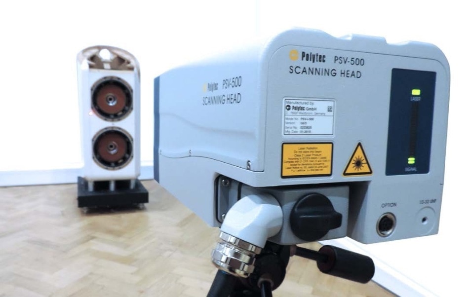
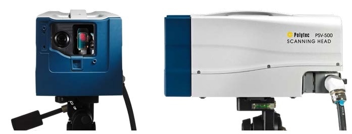
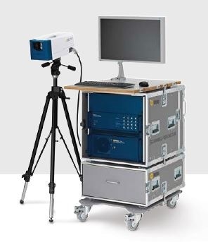
Polytec’s PSV-500 scanning vibrometer for non-contact measuring of structure vibration.
Innovative Measurement Technology for an Innovative Product
"Non-contact measurement technology with high spatial resolution is essential to capture the product’s performance."
Non-contact and full-field vibration sensing technology enables probing the spatial resolution that is needed for a meaningful validation of the simulation results. The automatic sequential scanning procedure allows no change in the instrumentation effort with increased measurement grid resolution. Traditional mounting of accelerometers could result in mass-loading of the structure, typically leading to loss in linearity caused by coupling resonances. The surface velocity is detected by the SLDV with no change in the mechanical properties of the loudspeaker cabinet. For the validation bandwidth of 10 kHz, the flat frequency response of the laser Doppler vibrometer is helpful because light does not experience coupling resonances.
The measurement grid can either be manually defined or, imported from the simulation model geometry. To consider phase relations between all measurement points, the driving voltage phase of the drive units is employed as a phase reference.
The two most important and largest radiating surfaces are the wrap and front baffle. Polytec’s laser Doppler scanning system was used to measure the velocity of each point on a user-defined grid over these surfaces.
Measurements Confirm Simulated Cabinet Performance
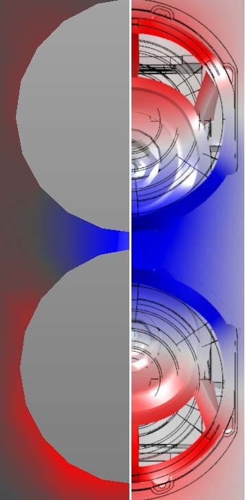
Measured modal shape at 222 Hz (left) and simulated modal shape at 281 Hz (right).
Validation is performed by comparing the measured acceleration magnitude spectra with the simulated values at critical locations. In order to facilitate this comparison, the finite element mesh from COMSOL was employed as a measuring grid for the Polytec laser. The modal shape for the first relevant mode is shown in Figure 4.
Simulation detects the main regions of significant peaks that are related to rigid body motion, the modes related to the front baffle and side wrap, and plate bending modes of the plinth.
The vibration amplitudes agree well between measurements and simulations. However, simulation overestimated the associated frequencies (Figure 5). This discrepancy can be due to the assumptions made in the simulation model, like the description of material properties as bulk properties or, the choice of boundary conditions.
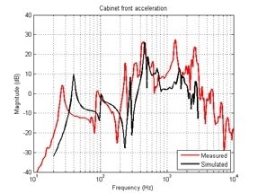
Cabinet front acceleration as a function of frequency from simulation (black line) and measurement (red line).
The development engineers of B&W are optimistic that, with an enhanced simulation model, the match of results could be improved. However, an improved simulation model will result in an improved cabinet design in terms of quality, as well as an increase in the development cost and time.
Within the scope of this work, the engineers came to the conclusion that the simulation results are adequate to predict the quality of the modeled loudspeaker cabinet design. The simulation also helps to probe into the physical effects which in this case leads to a better knowledge of how different panel placements influence the cabinet’s performance and how different vibration modes couple.
Conclusion
"Simulations are images of reality, measurements are observations of reality. Combining both methods reveals the full information about the system."

Simulations are images of reality, offering a cluster of physical parameters at each grid point. Their accuracy depends on the accuracy of the underlying mathematical model, the numerical method, the accuracy of the input parameters and the computational effort. Measurements are observations of reality, and show the effects that may not have been included in the simulation but require working prototypes as observable objects. Apart from measurement errors, some quantities are not accessilble by measurements. Additionally, all observed effects cannot be readily explained as it might be difficult to control the measurement conditions in the case of some observed effects.
Hence, the full information about the system can be revealed only by the combination of the two methods. The comparison of the simulation model with measurements can identify the dominant and relevant physical phenomena involved, and therefore, get a deeper understanding of the system behavior so as to guide the design effort.
After completing the set-up of a single model capable of reproducing all relevant data within the required accuracy, the model can be employed to automatically batch-process all the material choices and design options.
For future projects, vibration measurements could be employed for models of acoustic propagation. In a purely acoustics model, the measured velocity distribution would be used as the input. Then, the sound pressure in any point in space generated by a sound source with acoustic environment and arbitrary surrounding objects can be predicted by the simulation software. Such an approach to the propagation problem would be facilitated by the ease of exchangeable data formats between measurement equipment and simulation software. Both Polytec and COMSOL Multiphysics offer the technology to realize this project.
References
- “Modelling the Sound Radiation by Loudspeaker Cabinets”, M. Cobianchi, Dr. M. Rousseau, B&W Group Ltd, Worthing, West Sussex, England, Comsol Conference 2014, Cambridge UK

This information has been sourced, reviewed and adapted from materials provided by Polytec.
For more information on this source, please visit Polytec.