The MEMS industry has been benefiting extensively from non-contact vibration testing (vibrometry) in troubleshooting, FE model correlation and performance validation of critical components in the micron scale. The real-time analysis of the mechanical motion, be it in the in-plane or out-of-plane direction or both, has been invaluable in the development of various types of MEMS devices. Such devices are PMUTs/CMUTs, inertial sensors, RF switches, MEMS microphones and pressure sensors, just to name a few. Polytec’s Micro System Analyzer (MSA) line of products has been serving these applications providing precise and reliable data from DC up to the several MHz and even into the GHz range.
Dynamic characterization of silicon encapsulated MEMS devices is a need that has recently emerged amongst the MEMS community. The performance of a device changes after encapsulation and it is therefore crucial to understand the behavior and performance of the device in its packaged form. Polytec’s MSA-650 IRIS uses a patented infrared (IR) technology to ‘see through’ the silicon cap and perform an accurate characterization of the MEMS device inside.
Highlights
- The IRIS offers a live video of the encapsulated device, which makes the setup and alignment fast and easy.
- The IR measurement beam transmits through the cap and reflects off the MEMS device making real-time vibration analysis possible in the encapsulated environment.
- The key in guaranteeing accurate results is the successful suppression of reflections from other surfaces in the beam path. Even a small percentage of reflected light from the cap can cause significant errors in the results, and that is the case even when the cap is not vibrating. The IRIS is using a patented approach with a short coherence light source to keep the unwanted reflections below a critical threshold.
- The IRIS produces high-resolution modal data up 25 MHz for out-of-plane motion (resolution below a picometer) and up to 2.5 MHz for in-plane motion (resolution down to 30 nanometers).
- Full field, real-time data on a grid of measurement locations can be acquired by means of high-precision piezo-driven steering mirrors.
- The IRIS can be integrated into an automated probe station in a production environment.
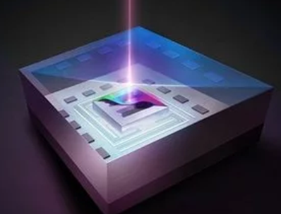
MSA-650 IRIS Micro System Analyzer principle measuring through MEMS caps. Image Credit: Polytec
Modal Testing of Silicon Encapsulated MEMS Accelerometers
An example of a vibration test with the IRIS is demonstrated in this article on a packaged 2-axis MEMS accelerometer, courtesy of the Fraunhofer Institute for Electronic Nano Systems (FHG ENAS). The image below shows the live image taken with the integrated short-wave IR (SWIR) camera. Two sets of comb-finger structures are arranged at a 90° angle to each other for detecting motion in two orthogonal directions. A 50x magnification objective was used resolving the 3µm wide comb fingers adequately.
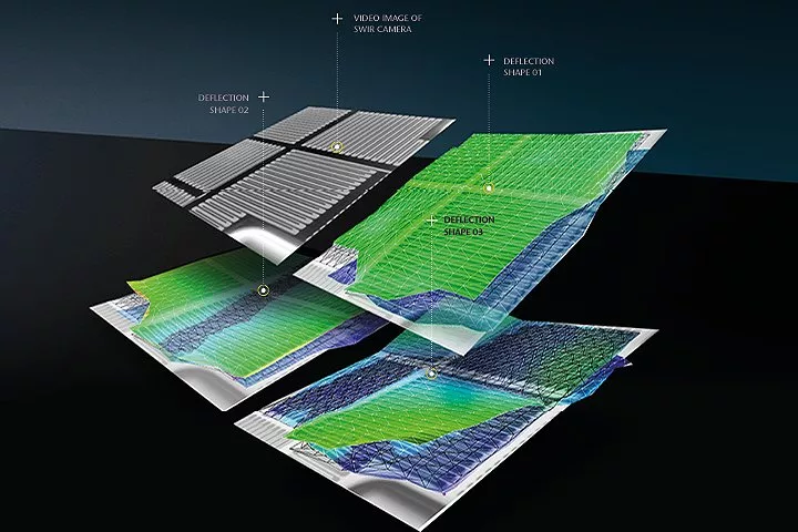
2-axis accelerometer (FHG ENAS) pure SWIR camera image plus operational deflection shapes captured with scanning laser Doppler vibrometer. Image Credit: Polytec
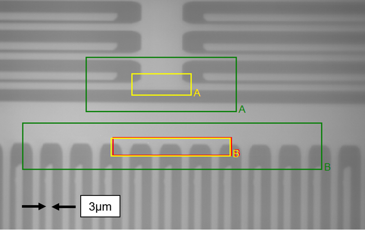
Live camera image of silicon encapsulated 2-axis MEMS accelerometer with the MSA-650 IRIS and a 50x magnification objective.
Planar motion is measured with a stroboscopic imaging method and pattern matching. Polytec’s smart algorithm allows for resolving displacements well below the size of a pixel. In the image above, pattern A was aligned to a stationary structure while pattern B was aligned to the moving comb structure. This constitutes a differential setup that removes any common mode vibrations present during the measurement.
The bode plot in the next picture shows the difference in response of patterns A and B over a frequency range from 500 Hz up to 10 kHz. This particular MEMS accelerometer was designed to exhibit a flat response up to 2 kHz, which is verified in the measured frequency spectrum.
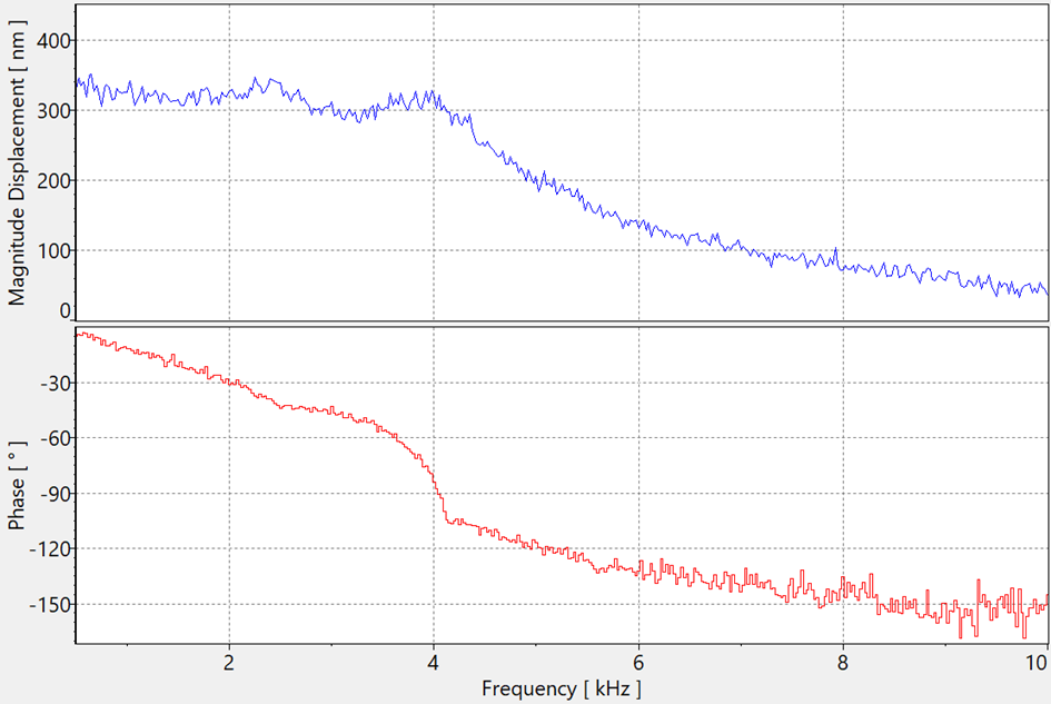
Bode plot obtained by video stroboscopy and pattern matching.
Even though this MEMS structure is designed to move in the in-plane directions only, it is important for design verification to validate the residual out-of-plane dynamics as well. This is achieved with IRIS’ Doppler vibrometer technology. A low-coherence super-luminescent diode (SLD) generates a measurement beam that is targeted at the MEMS structure. The reflected return light is Doppler-shifted in frequency carrying the velocity information of the moving object.
The spectrum below shows the average frequency spectrum across an entire scan grid capturing resonances beyond the 1 MHz mark. The plot is displayed in logarithmic scale with the 0 dB reference set at 1 m and -240 dB corresponding to 1 picometer. In this measurement the noise floor was well below 1 picometer.
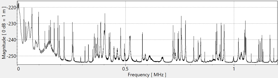
Average frequency spectrum in displacement of the out-of-plane response with sub-picometer resolution.
High-precision steering mirrors inside the IRIS head enable the acquisition of an aerial grid of points at high speed. The acquisition is done sequentially, and the individual data sets are then combined to create deflection shape animations. The next image shows the deflection shape at the 4 select resonances: 194 kHz, 355 kHz, 941 kHz and 1.05 MHz. Approximately 6,500 points have been measured across the entire MEMS structure. Some of the points were on the moving comb fingers while others were placed on stationary structures for reference.
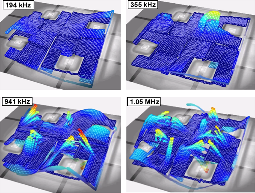
Deflection shapes of the encapsulated MEMS accelerometer.
For validating MEMS designs, vibration data on the encapsulated device as shown here is critical for achieving accurate model validation and for an efficient design iteration in product development.
Test Setup
For laboratory environments the MSA-650 IRIS is mounted on a work bench with a 5-axis positioning stage. Signal generator, data acquisition and software interface are included. The software is custom designed for ease-of-use during the measurement process and for data presentation and interpretation.
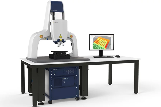
MSA-650 IRIS system on a laboratory work bench with 5-axis positioning stage.
The MSA-650 IRIS is compatible with probe stations for automation of the measurements in a production environment and for waver-level testing. The software’s API allows the integrator to fully interact with the IRIS functionality.
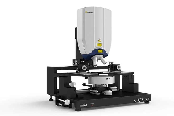
Polytec MSA-650 IRIS integrated into a MPI probe station.
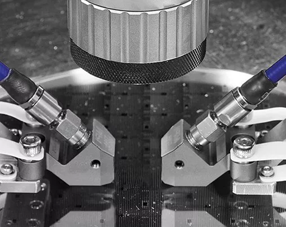
Probe station integration for MEMS measurement on wafer-level.
Leading Technology in MEMS Dynamic Characterization through Silicon Caps
The key to successful measurements through capped devices is the capability to efficiently isolate the surface of interest (MEMS structure) and reject the reflections from any other surfaces. As indicated in the image below (left side), the reflectivity of the silicon cap at 1550 nm is 31% on the top side and 15% on the bottom side. The reflection of interest from the MEMS’ top surface is only 7%, which is quite small compared to all the adjacent unwanted reflections.
Polytec’s patented optical setup is powered by a short coherent light source in combination with confocal optics achieving a 10-6 rejection rate for any surface that is 20 microns away from surface of interest (see right side of image below). Such high rejection rate is crucial in obtaining accurate measurement data.
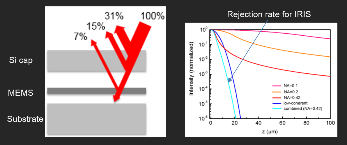
Light reflectivity of different surfaces in % (left). Intensity rejection rate of adjacent surfaces (right) for confocal systems (NA 0.1 to 0.42) and low coherent systems.