Andor manufactures a comprehensive range of CCD detection systems for a wide variety of x-ray applications, both imaging and spectroscopy. These detection systems can be used at varying energy levels and are custom configured to operate either directly in a vacuum chamber, attached to a chamber via a Conflat flange or "stand-alone". In addition, if your application requires indirect detection of x-ray, Andor offers a range of fibre-coupled cameras.
Applications that benefit from Andor's high-end X-ray detection solutions include:
- X-ray/gamma tomography
- X-ray spectroscopy
- X-ray microscopy
- X-ray beam profilometry
- X-ray diffraction
- Lithography
- X-ray topography
- Plasma Studies
- Medical imaging
- Thomson Scattering
The X-ray spectrum can be approximately divided into several regions. These regions are not separated by a well defined boundary, however for the purposes of this overview they are defined as:
- VUV to XUV = 0.01 - 0.1 keV
- XUV to Soft X-ray = 0.1 - 1 keV
- Soft to Hard X-ray = 1 - 10 keV
- Hard X-ray = 10 - 100 keV
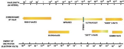
Electromagnetic Spectrum
Equation 1 - 10Å = 1nm and λ(Å) = 12.4 / E(keV)
Electron Multiplying CCD (EMCCD) X-ray Innovation
The latest pioneering innovation for indirect X-ray detection is fibre-coupled EMCCD technology, enabling single photon sensitivity of high-energy X-rays across large area demagnifying fibres, at rapid multi-MHz readout speeds!
Direct Detection
With direct detection cameras, the CCD sensor itself is exposed to the incoming illumination. This enables photons to be absorbed directly in the sensitive depletion region of the CCD sensor, often creating several electron hole pairs. Compared to indirect detection and traditional X-ray film detection, this method boasts:
- Higher Quantum Efficiency (QE)
- Single photon sensitivity without EMCCD & ICCD
- Better spatial & energy resolution
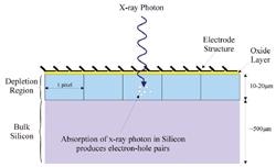
Absorbtion of X-ray photon in silicon
Quantum Efficiency of Direct Detection Cameras
QE is the probability of a photon being detected by a CCD sensor. Remember however that in direct detection of X-ray illumination, several photoelectrons of signal are created from a single impinging photon, often yielding single photon sensitivity. The number of photoelectrons formed is related to the energy of the photon, as given by Equation 2. The figure below shows QE curves for a number of direct detection sensor options.
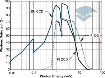
QE curves for a number of direct detection sensor options
Equation 2 - No of photoelectrons generated in a direct detection pixel = X-ray photon energy (eV) / 3.65
FI is a front illuminated device and FI-DD indicates availability of a deep depletion option, offering improved hard X-ray response over FI. BN is a back illuminated option that has no anti-reflection coating (as opposed to BV codings as shown elsewhere on this site), providing the best QE available for soft to medium X-ray detection. Apart from the higher QE of back illuminated sensors, they have another important advantage over front illuminated systems: they provide significantly better protection against possible degradation of the sensor by over-exposure to energetic X-rays. Back illuminated sensors are the recommended device for your direct detection requirements.
Table 1. Advantages & Disadvantages of Direct Detection CCD's
|
Advantages
|
Disadvantages
|
|
Good spatial resolution
|
Cannot detect hard X-rays > 20keV
|
|
Single photon sensitivity
|
Upper limit on image area (typically ~ 25 x 25mm)
|
|
Energy resolution
|
CCD "damages" progressively by energetic X-ray
|
|
Good QE
|
|
|
Linear response
|
|
|
High dynamic range
|
|
Indirect Detection
Indirect detection is used for hard X-ray detection and when you need:
- Single photon sensitivity even with highly demagnifying tapers (EMCCD technology available)
- QE coverage that stretches well into the hard x-ray region
- Large area coverage (via magnifying taper)
- High dynamic range at high energy levels
- Protection of the CCD sensor
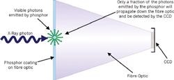
With indirect detection CCDs, a phosphor coating on a fibre optic converts X-ray photons to visible photons. Characteristics of an indirect detection device, such as QE and spatial resolution, will depend on the parameters of the phosphor selected, such as thickness of the layer, chemical composition and particle size.
Indirect detection with phosphor-coated removable magnifying taper
A novel method of phosphor deposition, developed with our suppliers, can be used on the fiber-optic of Andor's indirect detection cameras, providing excellent spatial resolution, up to four times better than traditional bulk deposition methods. The phosphor coating may be tailored to meet your requirements.
Use of a phosphor coated fibre optic is the best option for protecting the CCD sensor against X-ray degradation. By solving the problem of poor phosphor spatial resolution, and enhanced sensitivity using EMCCD, much more effective indirect detection capabilities can now be achieved for energies lower than 5keV.
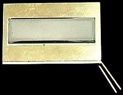
Example of a fiber optic spectroscopy sensor overcoated with GdO phosphor
The figure below illustrates how the overall gain of a typical phosphor coated fibre optic camera varies with incident photon energy. The system gain is defined as the number of detected electrons per incident X-ray photon. The gain of the system will vary depending on the type, thickness and grain size of the phosphor. It also depends on the QE of the CCD sensor and the fibre optic used.
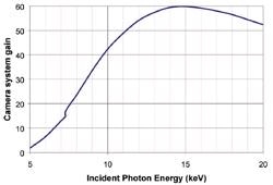
Overall gain of a typical phosphor coated fibre optic camera
This particular example is for a phosphor coated 1:1 fibre optic. The phosphor has been optimized to operate over an energy range of 5 to 25 keV, peaking at ~ 15 keV. For large area demagnifying fibre tapers, the overall gain becomes substantially less and EMCCD technology can be used to amplify the weak signal above the readout noise floor of the detector, even at rapid multi-MHz readout speeds – ideal for fast tomographic applications for example.
Table 2. Advantages & Disadvantages of Indirect Detection
|
Advantages
|
Disadvantages
|
|
Higher dynamic range
|
Lower spatial resolution
|
|
EMCCD compatible – single photon sensitivity
|
Lower Energy resolution
|
|
Large area magnifying tapers
|
|
|
CCD protected by fibre-optic
|
|
|
Wide photon energy coverage
|
|
Table 3. The Andor X-ray Range
| Code |
Description
|
Direct/Indirect
|
| DO |
Coupled to outside vacuum chamber
|
Direct + Indirect
|
| DX |
Inside vacuum chamber
|
Direct + Indirect
|
| DY |
Stand alone
|
Direct + Indirect
|
| DV |
VUV/XUV (to 120nm) MgF2 window
|
Direct
|
| DF |
Multi-MHz readout with phosphor-coated fibre taper (EMCCD available)
|
Indirect
|
Andor supplies a wide range of dedicated CCD and EMCCD cameras for direct and indirect detection of X-ray, in both spectroscopic or imagng sensor formats. Camera platforms are available to accommodate and optimize a range of sensor sizes and types, from 128 x 128 EMCCD through to 2048 x 2048 CCD. Andor's X-ray camera range has been developed to adapt to a range of experimental configurations, and systems are available that are stand-alone, coupled to outside of vacuum chamber, or can be incorporated inside the vacuum chamber.
High Energy Detection
Building on its over two decades of experience in cutting-edge development and manufacture, Andor offers an extensive range of high-energy camera detection systems that are suitable for a number of spectroscopy and imaging applications, such as medical research, material analysis and cell structure studies. They include both direct and indirect detection systems and can be operated at varied energy levels. It is also possible to configure them to be operated across various sampling interfaces.
A range of standard mounting flanges are available to interface the cameras with the vacuum chamber. Interfacing with external scintillators or imaging relays such as streak tubes can also achieved through fiber-optic coupled configurations.
These high-energy detection platforms are designed to be durable and user-friendly. Each system is engineered to be integrated rapidly and directly into the core of an experimental setup. As a specialist in bespoke customization, Andor also provides unique detection solutions to meet the specific experimental needs of its customers.
| Model |
Active Pixels |
Cooling |
Pixel Szie |
Read Noise |
| Zyla sCMOS HF |
2560x2160 |
0 |
6.5x6.5 |
0.9 |
| iKon-L HF |
2048x2048 |
-35 |
13.5x13.5 |
4.9 |

This information has been sourced, reviewed and adapted from materials provided by Andor Technology Ltd.
For more information on this source, please visit Andor Technology Ltd.