Glasses-free, three-dimensional (3D) displays are promising technologies that will redefine the display industry. However, a few issues such as limited motion parallax, short range of viewing distance, vergence—accommodation conflict, and self-repeating views hinder the widespread usage of 3D displays.
Multilevel diffractive optical elements (DOEs) are designed and fabricated for 3D displays. Like metagratings, multilevel DOEs have the same merit with high-level light manipulation capability to accommodate a large field of view (FOV), eliminated cross talk, and a thin form factor. At a wavelength of 850 nm, extremely large DOF from 5 to 1200 mm can be obtained.
The current study showed that with an appropriate design of the gray-scale diffractive lens (GDL), the DOF can be significantly extended at the green, red, and blue wavelengths of 532 nm, 450 nm, and 658 nm, respectively. It also proposed a vector light field 3D display with a pixelated GDL array. In a 4-in prototype, DOF enhancement was 1.8 × 10⁴-fold while the DOF itself ranged from 24 to 90 cm.
The cross-talk was kept to less than 26% over a viewing distance of 66 cm. The study also showed that a pixelated GDL significantly increases the viewing distance for vector light field 3D displays.
Methodology
Flat lenses for glasses-free 3D displays are difficult to design and manufacture. Mobile phone viewing distances typically range from 25 cm to more than 60 cm. The proposed GDL for 3D displays required an enhancement of DOF (eDOF) more than 9 × 10³-fold.
Other considerations include color fidelity for display purposes and the size of the optical device. The sawtooth relief profile of a GDL was optimized according to a directed binary search technique. A conventional Fresnel diffraction integral was adopted to simulate the x − z light distribution between the lens plane and the observation plane.
The light distribution of the GDL was analyzed by finite-difference time-domain analysis. The two simulation results suggested similar optical properties, thus validating the theoretical design. For achieving the feasibility of the proposed methodology, a GDL was designed and fabricated with ƒmin = 20 mm and ƒmax = 110 mm at specified wavelengths. The specified wavelengths were 658 nm, 532 nm, and 450 nm to depict the RGB imaging behavior.
Figures 1a–c illustrate the 3D topography and the flat lens’s surface relief profile. Figure 1d illustrates a micrograph of the GDL. The sawtooth has a minimum width of 35 µm. Figure 1e illustrates a 10 mm diameter GDL placed on top of a Soochow University logo.
The intensity distribution of light in the x − z plane was simulated and plotted for the conventional Fresnel lens and the proposed GDL, as shown in Figures 1f–g. There are several focal points in the �� direction within the main lobe of focus. However, the Fresnel lens has a single focal point when the focal length is 50 mm.
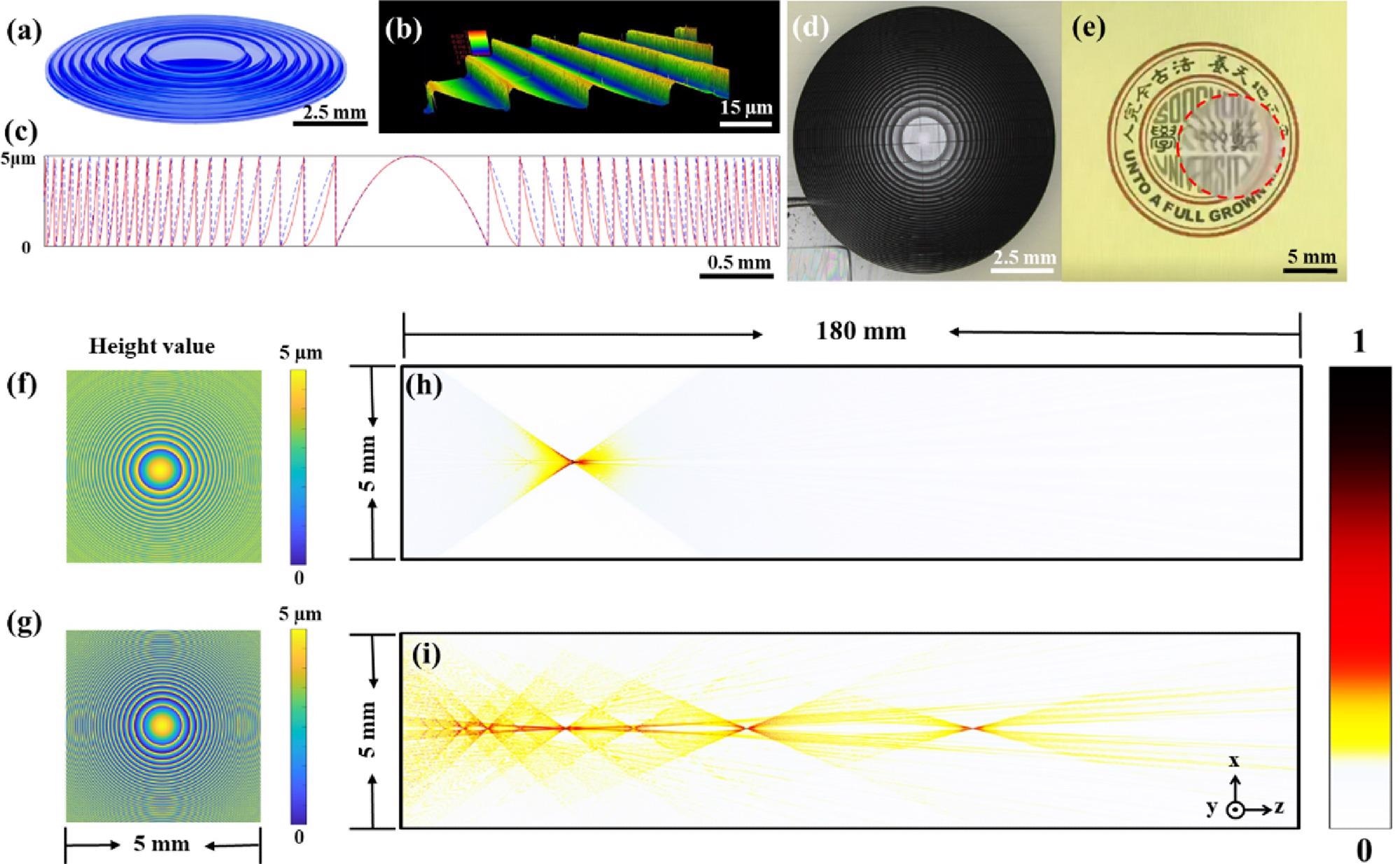
Figure 1. 3D topography of the flat lens and the comparison between the Fresnel lens and GDL. (a) 3D topography of the GDL; (b) 3D microscopic photo of the GDL captured by a laser confocal microscope (LEXT, OLS4100, OLYMPUS); (c) cross section of the traditional Fresnel lens (in blue) and optimized GDL (in red); (d) optical micrograph of the fabricated GDL; (e) imaging properties of the GDL; (f) topography of a Fresnel lens; (g) optimized topography of the GDL; (h)-(i) comparison between the light distributions of a Fresnel lens and the proposed GDL. Image Credit: Zhou, et al., 2022
The light distribution was further analyzed under the illumination of collimated light. Figures 2d–f illustrate the measured modulation transfer function (MTF) for the GDL. While the traditional Fresnel lens had a narrow spectral response, the GDL within the extended focal length range possessed identical optical behavior for RGB wavelengths.
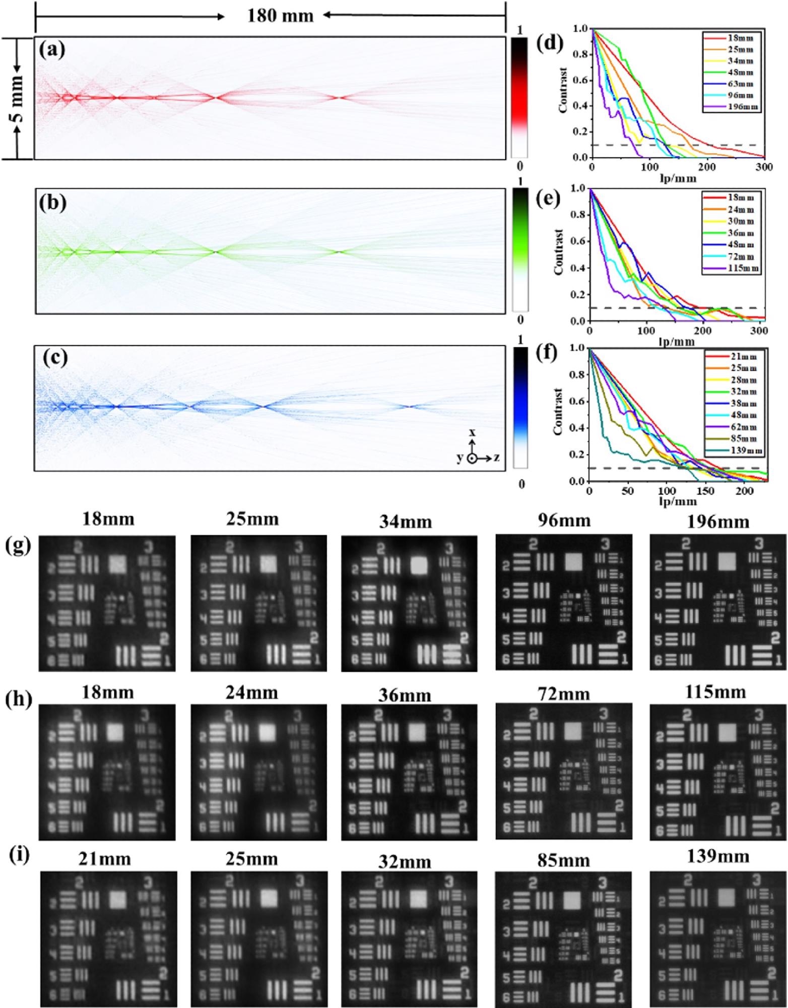
Figure 2. (a)-(c) Distribution diagram of far-field diffraction light intensities at the wavelengths of 658, 532, and 450 nm. (d)-(f) Modulation transfer function for the GDL at the illuminance of red, green, and blue, respectively. (g)-(i) Image of the Air Force resolution chart at the different z distance under the illuminance of red, green, and blue, respectively. Image Credit: Zhou, et al., 2022
Results and Discussion
The study proposed a vector light field 3D display in which the vector of the light beam from the pixels forms a converged view.
The vergence—accommodation conflict is appreciably reduced by converged views. A liquid crystal display (LCD) plays the role of a refreshable image generator. The matching surface-relief structures modulate the vector of the beam emerging from each pixel. The pixelated structures are ranged with the pixels of LCD panels. Multiple intertwined GDLs create multiple views to form motion parallax (Figure 3a).
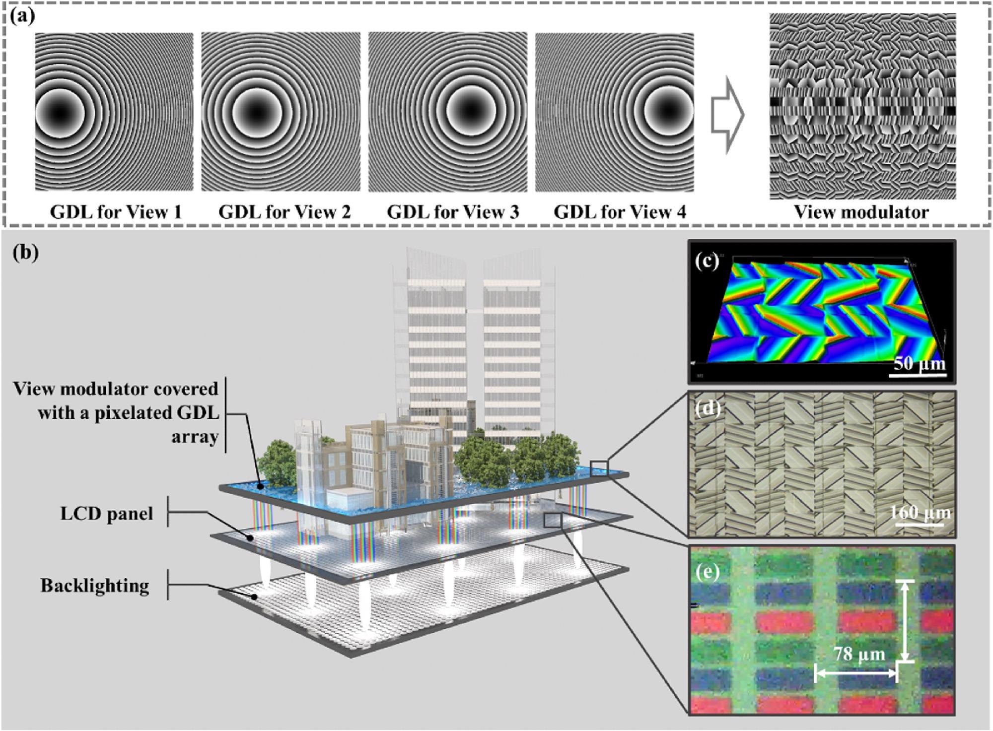
Figure 3. Schematic diagram of the 3D display device. (a) Schematic of the pixelated GDL array. (b) Vector light field display device. (c), (d) Microscope picture of the view modulator. (e) Microscope picture of the pixel size. Image Credit: Zhou, et al., 2022
In comparison with an MLA-based 3D display, a view modulator having an intertwined GDL is better for dramatically reduced information redundancy. Figure 3b schematically shows a vector light field 3D display according to a pixelated flat lens array. Figure 3e illustrates the color filter of an LCD panel having a pixel size of 78 µm, on which several perspective images are refreshed at video rate.
Pixelated GDL arrays on the view modulator were fabricated using a gray-scale lithography system. An ultraviolet imprinting process is performed to transfer the surface relief structures to a flexible membrane. The pixel size of the microstructures is set at 78 µm to enable pixel-to-pixel integration with the LCD panel.
The DOF of the view modulator was tested with collimated white LED light. Four converged views were captured when the receiving plane shifts away from the view modulator at distances ranging from 24 to 90 cm (Figure 4a). The light distribution in the z-direction is evaluated by cross talk and DOF.
![(a) Intensity distribution of four views at distances from 12 to 90 cm. (b) Light intensity distribution of the four viewpoints at a distance of 48 cm. (c) Measured cross-talk dependences on viewing distance compared with prior art [33]. (d) Measured light efficiency under collimated LED illumination.](https://d36nqgmw98q4v5.cloudfront.net/images/Article_Images/ImageForArticle_2199_16494251784224776.jpg)
Figure 4. (a) Intensity distribution of four views at distances from 12 to 90 cm. (b) Light intensity distribution of the four viewpoints at a distance of 48 cm. (c) Measured cross-talk dependences on viewing distance compared with prior art [33]. (d) Measured light efficiency under collimated LED illumination. Image Credit: Banerji, et al., 2020; Zhou, et al., 2022
The color fidelity and color mixing of the view modulator was tested (Figure 5c) after the integration of the 4-inch view modulator with an LCD panel, as shown in (Figures 5a and 5b). The natural motion parallax is observed in Figures 5d–f.
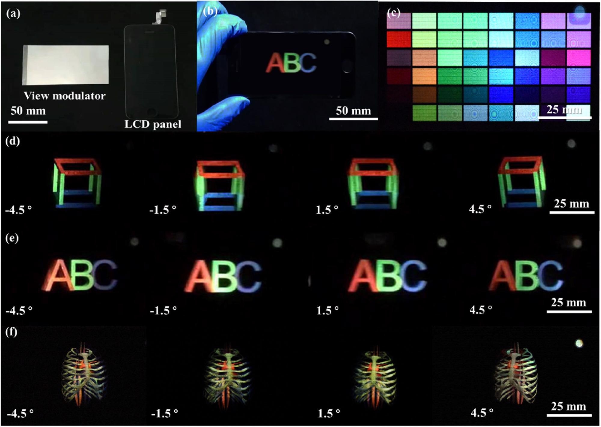
Figure 5. (a) Photos of the view modulator and LCD panel. (b) Photo of the vector light field 3D display prototype. (c) Color block matrix diagram observed at the viewpoints. (d)-(f) Images observed from different perspectives. Image Credit: Zhou, et al., 2022
Conclusion
In this study, published in Optica, a delicate design of a GDL was used to regulate the light field to form converged views over an extended DOF with better spatial resolution. The study also proposed a vector light field 3D display in which the vector of the light beam from the pixels forms a converged view.
It was demonstrated that an intertwined GDL enlarged the viewing distance for vector light field 3D displays. The slight cross-talk that was observed can be further reduced by improving the fabrication and assembly processes.
The glasses-free 3D display is a new use for metalenses and diffractive lenses. The design of flat lenses in the 3D display is not as critical as that in imaging applications.
Journal Reference
Zhou, F., Zhou, F., Chen, Y., Hua, J., Qiao, W., Chen, L. (2022) Vector light field display based on an intertwined flat lens with large depth of focus. Optica, 9(3), pp. 288–294. Available Online: https://opg.optica.org/optica/fulltext.cfm?uri=optica-9-3-288&id=470234.
References and Further Reading
- Nam, D., et al. (2017) Flat panel light-field 3-D display: concept, design, rendering, and calibration, Proceedings of the IEEE, 105, pp. 876–891. doi.org/10.1109/JPROC.2017.2686445.
- Fattal, D., et al. (2013) Beausoleil, A multi-directional backlight for a wide-angle, glasses-free three-dimensional display, Nature, 495, pp. 348–351. doi.org/10.1038/nature11972.
- Wetzstein, G., et al. (2012) Compressive light field displays, IEEE Computer Graphics and Applications, 32, pp. 6–11. doi.org/10.1109/MCG.2012.99.
- Liu, M., et al. (2017) Near eye light field display based on human visual features. Optics Express, 25, pp. 9886–9900. doi.org/10.1364/OE.25.009886.
- Jang., C. (2017) Retinal 3D: augmented reality near-eye display via pupil-tracked light field projection on retina. ACM Transactions on Graphics, 36, p. 190. doi.org/10.1145/3130800.3130889.
- Li, K., et al. (2017) Full resolution auto-stereoscopic mobile display based on large scale uniform switchable liquid crystal micro-lens array. Optics Express, 25, pp. 9654–9675. doi.org/10.1364/OE.25.009654.
- Kim, C. J., et al. (2015) Depth plane adaptive integral imaging using a varifocal liquid lens array. Applied Optics, 54, pp. 2565–2571. doi.org/10.1364/AO.54.002565.
- D. Teng., et al. (2015) Multiview three-dimensional display with continuous motion parallax through planar aligned OLED microdisplays. Optics Express, 23, pp. 6007–6019. doi.org/10.1364/OE.23.006007.
- Rivenson, Y., et al. (2019) “Deep learning in holography and coherent imaging,” Light: Science & Applications, 8, pp. 85–92. doi.org/10.1038/s41377-019-0196-0
- Tay, S., et al. (2008) An updatable holographic three-dimensional display,” Nature, 451, pp. 694–698. doi.org/10.1038/nature06596.
- Blanche, P. A., et al. (2010) Holographic three-dimensional telepresence using large-area photorefractive polymer Nature, 468, pp. 80–83. doi.org/10.1038/nature09521.
- Butt, H., et al. (2012) Carbon nanotube based high resolution holograms. Advanced Materials, 24, pp. OP331–OP336. doi.org/10.1002/adma.201202593.
- Yue, Z., et al. (2017) Nanometric holograms based on a topological insulator material Nature Communications, 8, p. 15354. doi.org/10.1038/ncomms15354.
- Kwon, K., et al. (2017) Enhanced depth-of-field of an integral imaging microscope using a bifocal holographic optical element-micro lens array Optics Letters, 42, pp. 3209–3212.
- Kwon, K., et al. (2017) Enhancement of the depth-of-field of integral imaging microscope by using switchable bifocal liquid-crystalline polymer micro lens array Optics Letters, 25, pp. 30503–30512. doi.org/10.1364/OE.25.030503.
- Yang, M., et al. (2019) Numerical simulation and experimental verification of a dense multi-view full-resolution autostereoscopic 3D-display-based dynamic shutter parallax barrier, Applied Optics, 58, pp. A228–A233. doi.org/10.1364/AO.58.00A228.
- Peterka, T., et al. (2008) Advances in the Dynallax solid-state dynamic parallax barrier autostereoscopic visualization display system. IEEE Transactions on Visualization and Computer Graphics, 14, pp. 487–499. doi.org/10.1109/TVCG.2007.70627.
- Kim, S. U., et al. (2016) Concept of active parallax barrier on polarizing interlayer for near-viewing autostereoscopic displays. Optics Express, 24, pp. 25010–25018. doi.org/10.1364/OE.24.025010.
- Huang, T., et al. (2019) High-performance autostereoscopic display based on the lenticular tracking method Optics Express, 27, pp. 20421–20434. https://doi.org/10.1364/OE.27.020421
- Le, Y., et al. (2018) Demonstration of an improved integral imaging with large viewing angle based on two crossed lenticular lens combined array. Optik, 172, pp. 578–584. doi.org/10.1016/j.ijleo.2018.07.005.
- Song, M. H., et al. (2016) Integral imaging system using an adaptive lens array. Applied Optics, 55, pp. 6399–6403. doi.org/10.1364/AO.55.006399.
- Le, Y., et al. (2018) A crosstalk-suppressed dense multi-view light-field display based on real-time light-field pickup and reconstruction. Optics Express, 26, pp. 34412–34427. doi.org/10.1364/OE.26.034412.
- G. Jason (2013) Three-dimensional display technologies. Advances in Optics and Photonics, 5, pp. 456–535. doi.org/10.1364/AOP.5.000456.
- Kan, B., et al. (2017) A 3D video visual comfort evaluation method on the consistency of accommodation and convergence. Optoelectronics Letters, 13, pp. 233–236. doi.org/10.1007/s11801-017-6199-2.
- Hua, J. Y., et al. (2021) Foveated glasses-free 3D display with ultrawide field of view via a large-scale 2D-metagrating complex. Light: Science & Applications, 10, p. 213. doi.org/10.1038/s41377-021-00651-1.
- Wan, W. Q., et al. (2020) Holographic sampling display based on metagratings. iScience, 23, p. 100773. doi.org/10.1016/j.isci.2019.100773.
- Shi, J. C., et al. (2020) Spatial multiplexing holographic combiner for glasses-free augmented reality. Nanophotonics, 9, pp. 3003–3010. doi.org/10.1515/nanoph-2020-0243.
- Zhou, F., et al. (2020) Pixelated blazed gratings for high brightness multiview holographic 3D display IEEE Photonics Technology Letters, 32, pp. 283–286.
- Hua, J. Y., et al. (2020) Multiview holographic 3D display based on blazed Fresnel DOE. Optics Communications, 472, p. 125829. doi.org/10.1016/j.optcom.2020.125829.
- Sochacki, J (1984) “Multiple-foci Luneburg lenses,” Applied Optics, 23, p. 4444–4449. doi.org/10.1364/AO.23.004444.
- Wu, Y., et al. (2018) Aydogan, Extended depth-of-field in holographic imaging using deep-learning-based autofocusing and phase recovery. Optica, 5, pp. 704–710. doi.org/10.1364/OPTICA.5.000704.
- Motogaito, A., et al. (2020) Fabrication and characterization of a binary diffractive lens for controlling focal distribution. Applied Optics, 59, pp. 742–747. doi.org/10.1364/AO.381139.
- Banerji, S., et al. (2020) Extreme-depth-of-focus imaging with a flat lens. Optica, 7, pp. 214–217. doi.org/10.1364/OPTICA.384164.
- Jung, S. M., et al. (2015) Numerical simulation of the displayed image on the entire screen of autostereoscopic displays. Optics Express, 23, pp. 1–14. doi.org/10.1364/OE.23.000001.