Mixed reality and augmented reality (MR/AR) devices share a common feature that differentiates them from virtual reality (VR) devices: they are transparent.
The trademark of VR devices is how they totally enclose the user’s field of view within the headset to produce an immersive virtual environment. In contrast, AR/MR headsets and smartglasses project images onto a clear display surface that allows the user to see through to the real world.
Waveguides in AR/MR Devices
Waveguides are thin pieces of clear plastic or glass with unique light-transmitting characteristics. This is the main technology that has allowed augmented visualization in AR/MR.
Already a well-known concept, waveguides have been utilized in several technology applications, for example, LED backlights, holograms, fiber optics, among others. In all forms, waveguides are utilized to direct electromagnetic waves in particular patterns, directions or shapes.
Optical waveguides in near-eye devices (NEDs) help combine and bend light to channel it into the eye and produce the virtual images observed by the wearer overlaid onto the environment.
The process of total internal reflection (TIR) is used to propagate a light field, where light is reflected between the outer and inner edges of the waveguide layer with limited light leakage.
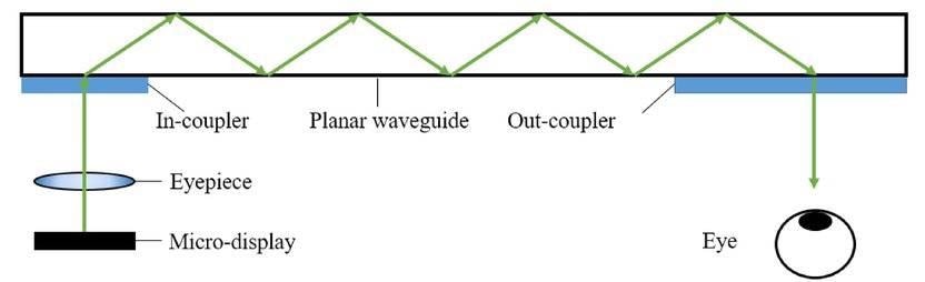
Schematic illustration of the mechanism of total internal reflection (TIR) for an AR device: a planar glass waveguide layer receives light via an input coupler (entrance pupil) and bounces it between the edges of the layer without losing (leaking) light until it reaches an output coupler (exit pupil). (Image Source)
VR headsets can present images from an imaging system or a projector located directly in front of the user, but AR/MR tools need ‘see-through’ functionality.
“The imaging system cannot block the front view, which therefore requires one or several additional optical elements to form an ‘optical combiner.”
“The optical combiner reflects virtual images while transmitting external light to human eye, overlaying the virtual content on top of the real scene, for them to complement and ‘augment’ each other.”1
Waveguide technology in a NED utilizes “an image projector tucked away out of the line of vision [to] projects the image into a small peripheral area of the display lens, then propagates it along the lens to an extraction point in front of the eye.”2
The waveguide essentially functions “as a transparent periscope with a single entrance pupil and often many exit pupils.”3
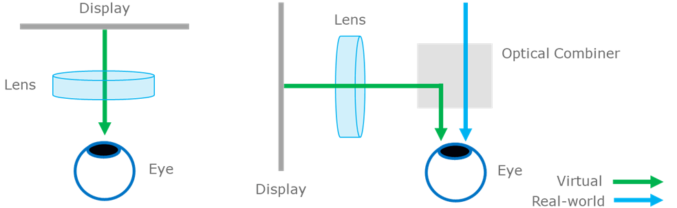
Comparing the configuration of a VR device (left) with display and optical modules (lens, projector, opaque display surface) directly in the user’s field of view, with an AR device (right) where a transparent optical combiner (waveguide) receives light input from the display and the real-world simultaneously, combining them to present the user with an integrated scene. Image Credit: Radiant Vision Systems
Waveguide Adoption
To increase adoption in the consumer marketplace, AR/MR devices need to have minimal bulk or weight and have a compact form factor, along with offering a high-quality image with a large field of view (FOV).
Optical combiners are found in various forms but, to date, waveguides are the only form that has been able to attain the optimal visual quality for AR.4 Waveguides have become the main element in several of the AR devices launched to market thus far, such as Magic Leap, HoloLens and more.
AR/VR device adoption has been on a growth trajectory that is predicted to speed up, from industry sales of US$ 17.67 billion in 2020 to over $26 billion by 2028, a CAGR of 4.3%.5
Around 65% of the market consists of head-mounted devices (HMDs), such as smart glasses.6 AR/MR applications in architecture and construction, education, navigation, and healthcare are inspiring consistent development and helping to increase the adoption of optical waveguides.
Waveguide Structures
Waveguides employed in AR/MR devices are normally glass substrates that can vary in thickness from the sub-nanometer to several nanometers.
Differences in the coupler and waveguide architecture and the application of surface coatings or gratings allow developers to produce virtually endless waveguide structures to suit various applications.
“The core of a waveguide combiner consists of the input and output couplers. These can be either simple prisms, micro-prism arrays, embedded mirror arrays, surface relief gratings, thin or thick analog holographic gratings, metasurfaces, or resonant waveguide gratings,”7 in addition to curved combiners, free-form optics, and beam splitters, all of which offer distinct weaknesses and benefits.
Optimized color images with a larger field of view can be achieved through the stacking of several waveguide combiners.
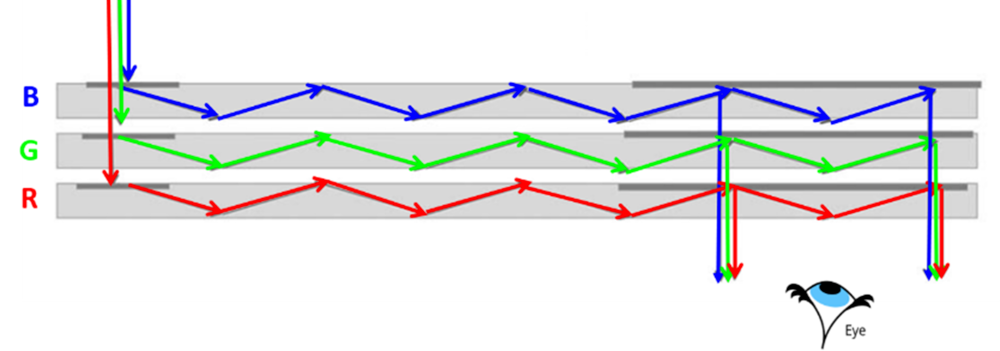
Schematic illustration of a multi-layer waveguide: each waveguide combiner layer transmits one portion (red, green, blue) of the light wavelength spectrum. Air gaps between each layer produce the desired TIR condition and allow for potential additional spectral or polarization filtering. Image Source: AR VR Journey
In contemporary HMD systems for AR/MR applications, four key types of waveguides are predominantly used:
Reflective
Reflective waveguides utilize a molded plastic substrate to direct the semi-reflective mirror and light waves in front of the eye.
Images are produced on a micro-display, enlarged by a collimating lens, and “the collimated light waves are transmitted to the semi-reflective mirror through the waveguide. Finally, the human eye sees the images reflected”8 onto the mirror and the real-world simultaneously.
Epson’s Moverio and Google Glass devices utilize waveguide structures of the reflective type.
Polarized
Also called transflective, polarized waveguides need several layers of polarized and coating reflectors, which are positioned in parallel and polished to effectively direct the waves of light. Lumus’ range of transparent AR products employed this type of waveguide.
Diffractive
Diffractive waveguides are the most commonly utilized waveguide structure for AR displays.
Incident light waves enter the waveguide at an angle due to slanted gratings, known as the in-coupler. The light passes through the waveguide and is drawn out at the exit pupil via an additional slanted grating, called the out-coupler.
The in- and out-couplers are normally created with a diffractive optical element (DOE) featuring slanted gratings. Magic Leap One, Vuzix Blade smart glasses and Microsoft HoloLens are some examples of devices that utilize a diffractive waveguide structure.
Holographic
These share a similar structure to diffractive waveguides, with holographic optical elements (HOEs) employed as the in- and out-couplers instead of DOEs.
Polychromatic (RGB) or monochromatic (RGB) light waves can be reflected by the HOEs. The HOE is created in the hologram recording process utilizing laser illumination with the incident angle
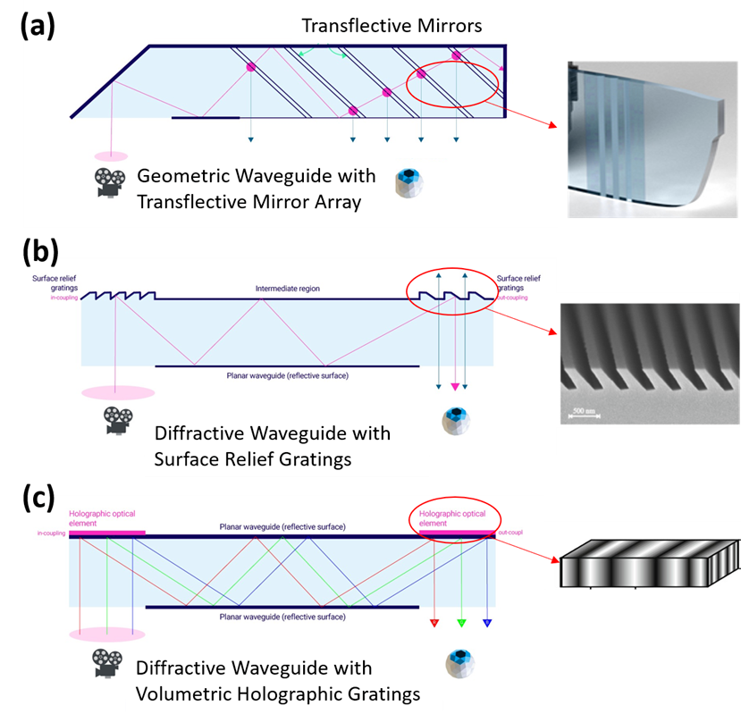
Schematic illustration of some common waveguide structures for AR/MR devices with corresponding images of grating structures: (a) polarized (transflective), (b) diffractive with surface gratings, and (c) holographic (diffractive with volumetric holographic gratings). Image Source: AR VR Journey
Within any diffractive waveguide, the key element is the grating, defined as a “periodic optical structure, whose periodicity can either be represented by the embossed peaks and valleys on the surface of the material, or by the ‘bright/dark’ fringes formed by laser interference in the holographic technology”.9
Measuring Waveguide Performance for AR/MR Devices
The physical features of an optical component, such as a waveguide or a lens, will always impact the light that is guided through the component to a certain extent.
By the time light has traveled to the user’s eye from an AR waveguide, it has already reflected through the optical structure several times, as determined by the diffraction effects of the grating, reflection and angle of incidence, and several other parameters.
This procedure influences optical efficiency, meaning that the light energy is decreased as it moves to the user’s eye from the source display.
This process can create poor contrast, clarity and brightness in the virtual image, as observed by the human eye. It is particularly crucial managing the quality of images in transparent NED designs, where superimposed images should be clear and visible to the user in various ambient lighting environments.
Diffractive waveguides are vulnerable to challenges with color tones in grayscale images, resulting in irregular color (chromaticity) and brightness (luminance) in the images.
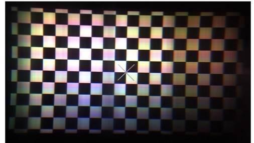
Projection from a diffractive waveguide exhibiting non-uniformity of both brightness and color tones on mid-level gray pixels. (Image Source).
A recent report10 showed how, according to the incident angle, even some roughness on the surface of the optical waveguide could decrease the display’s image quality, as quantified by an MTF (modulation transfer function) investigation.
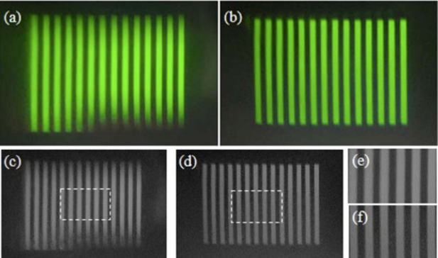
Images from a study of effects of incident angles on the waveguide surface. (a) and (b) are 65° and 75°, respectively. Grayscale images (c) and (d) correspond to images (a) and (b). MTF calculations are made in areas (e) and (f). (Image Source)
During development, one technique to investigate waveguide performance is to transmit light through it from a picture generating unit (PGU) or a light source.
The resulting image can then be assessed using a range of measurements, for example, sharpness, uniformity, color (chromaticity) and brightness (luminance).
Colorimetric imaging systems are a practical instrument for recording absolute values that assist in directing optical design.
Radiant’s ProMetric® I-Series Imaging Colorimeters can quantify parameters such as chromaticity and luminance and assesses these values throughout the complete image to establish uniformity.
As the measurement values are quantifiable, numerical data can be employed to compare quality over design iterations, according to various structural modifications to the waveguide.
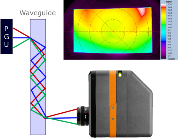
A picture generating unit projects an image through the waveguide; output is measured by ProMetric Imaging Colorimeter and analyzed using TT-ARVR™ Software (upper right, example analysis image shown in false-color scale). Image Credit: Radiant Vision Systems
Presented by Radiant in collaboration with Photonics Media, the below webinar offers support on optical performance testing for MR/AR/VR devices and elements like waveguides. Watch the webinar “Novel Solutions for XR Optical Testing: Displays, Waveguides, Near-IR, and Beyond” to learn about measurement technologies that mimic the human eye and improve testing speed, ease of use and accuracy at each phase of XR component production and development.

Image Credit: Radiant Vision Systems
References
- “Understanding Waveguides: the Key Technology for Augmented Reality Near-eye Display (Part I).” Virtual Reality Pop, Jun 18, 2019
- Ibid.
- Kress, B., “Optical waveguide combiners for AR headsets: features and limitations.” Proceedings of SPIE 11062, Digital Optical Technologies of 2019, 11062J (16 July 2019); doi: 10.1117/12.2527680
- Sprengard, R., “Waveguides propel augmented reality to consumers.” Laser Focus World, March 24, 2021.
- Augmented Reality Market Size, Share & Trends Analysis Report By Component, By Display (HMD & Smart Glass, HUD, Handheld Devices), by Application, By Region, And Segmented Forecasts, 2021-2028. Report by Grand View Research, February 2021.
- Ibid.
- Kress, B., “Optical waveguide combiners for AR headsets: features and limitations.” Proceedings of SPIE 11062, Digital Optical Technologies of 2019, 11062J (16 July 2019); doi: 10.1117/12.2527680
- Erdenebat, M., et al., “Waveguide-Type Head-Mounted Display System for AR Application.” Chapter 13 in State of the Art Virtual Reality and Augmented Reality Knowhow, IntechOpen, March 20, 2018, Nawaz Mohamudally, Ed. DOI: 10.5772/intechopen.75172
- “Understanding Waveguides: the Key Technology for Augmented Reality Near-eye Displays (Part II).” AR VR Journey, September 23, 2019
- Kuang, Y., Liu, J., and Shi, X., “Effect of surface roughness of optical waveguide on imaging quality and a formula of RSE tolerance and incident angle.” Optics Express, Vol 28 (2): 1103-1113, 2020. Doi: 10.1364/OE.382804
Acknowledgments
Produced from materials originally authored by Anne Corning from Radiant Vision Systems.

This information has been sourced, reviewed and adapted from materials provided by Radiant Vision Systems.
For more information on this source, please visit Radiant Vision Systems.