The uEye LE AF board-level cameras and other autofocus-capable industrial cameras from IDS have benefitted from a new type of contrast-based autofocus. This innovative new technology has also extended their application range.
The technology’s automatic focus is based on the active liquid lens control common to these camera models. It works when triggered in single-shot mode, as well as when used as a continuous focus control.
It is possible to individually configure the autofocus control according to the application in question, ensuring perfectly focused images in virtually every scenario.
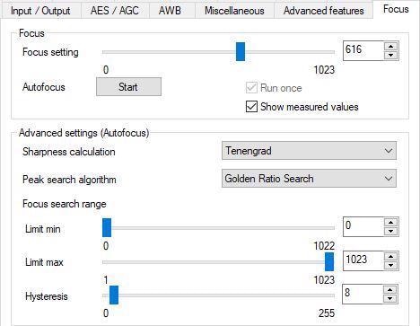
Focus dialogue window in the uEye Cockpit. Image Credit: IDS Imaging Development Systems GmbH
Automatic Focus Control
Version 4.93 of the IDS Software software introduced an automatic, software-based focus control feature to the uEye LE AF board level camera.
This supplements the previously manual liquid lens control and opens up many more possibilities for employing the cameras, particularly in applications dealing with variable object distances.
The size and position of the region of interest are adjustable, and various image sharpness measurement algorithms are available, each offering an array of configuration options.
These features help ensure fast and reliable determination of maximum image sharpness in the desired focus range, regardless of the situation or application.
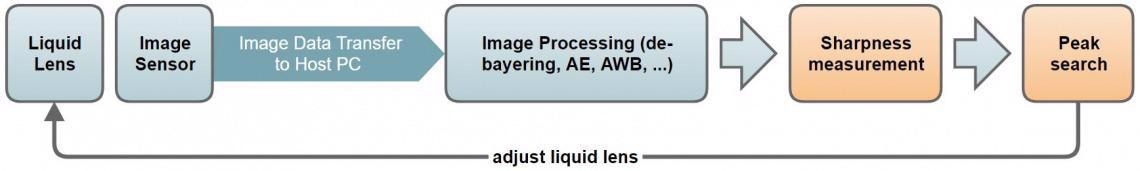
Image Credit: IDS Imaging Development Systems GmbH
The IDS Software Suite 4.93 manual details the general use of the focus automatic of the uEye LE USB 3.1 Gen 1 AF. Configuration options found in the uEye cockpit focus dialogue can also be used in users’ own applications via the uEye API function is_Focus().
The manual includes detailed information on this function, providing the full range of interface parameters alongside source code samples.
Automatic Focus Functionality
The autofocus function automatically adjusts the camera lens to the correct object distance in order to ensure a sharp image. The autofocus system employs the liquid lens control of the uEye LE AF board level camera, allowing this to focus at different distances.
In single-shot mode, the autofocus is triggered by the software and will only function until the maximum sharpness has been determined for the measuring window, deactivating itself at this point.
In continuous operation mode, however, image sharpness is measured on an ongoing basis with the lens continually readjusted as necessary.
The autofocus function controls the camera’s liquid lens based on image data analysis performed on the host PC. This occurs in a closed loop.
Determining the Sharpness Maximum via a Closed Control Loop
When working with closed-loop autofocus, the liquid lens and pixel path setting (for example, contrast and binning) will directly impact the image content, therefore affecting the sharpness measurement result of the image. This evaluation forms the basis for adjustment of the liquid lens prior to the acquisition of the next image.
It is not possible to calculate the optimum focus value at once using this image-based method, meaning that the closed control loop - including image acquisition, measurement, and focal length adjustment - must be passed through a number of times.
Analysis of the value pairs determined from the focus value and calculated image sharpness is used to ascertain the best possible (maximum) image sharpness in the relevant focus field.
Measuring Image Sharpness
There are different approaches to measuring image sharpness, and these methods are based on two fundamental principles.
The first of these principles is edge sharpness. A search is performed in the image content, looking for large gray value jumps between adjacent pixels. This enables edges or contours to be highlighted, and the contrast of these edges or contours provides useful information on the sharpness of the image.
Essentially, clearer edge images will imply a higher degree of sharpness in the original image.
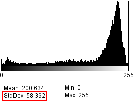
Large grey value spread. Image Credit: IDS Imaging Development Systems GmbH
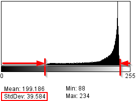
Low grey value spread. Image Credit: IDS Imaging Development Systems GmbH
The second of these principles is based on the analysis of the image’s histogram values. The standard deviation can be employed in calculating a measure for the variation of the pixel values around the average gray value of the image.
The greater the variance, the higher the existing gray value edges and the contrast of the image. Should the image become unfocused, the large gray value jumps (edges) take on a gradient in the form of a ramp.
This variation results in the contrast of the image decreasing, and this essentially means that a sharper image will have higher grayscale spread and, therefore, higher contrast.
Object surfaces are rarely ideal for optical focus measurements in practice, however. This approach tends to lead to unreliable and unstable measurement results. To circumvent this common problem, the uEye software's automatic focus function offers a range of measurement methods for specific image situations.
Algorithms such as Mean Score and Tenengrad facilitate analysis of image data using the principle of edge sharpness. The algorithms will analyze pixel by pixel, assessing relationships between direct neighboring pixels.
Mean Score employs more straightforward pixel calculations and a smaller neighborhood than Tenengrad. This results in a more rapid analysis but also more noise sensitivity.
The Histogram Deviation algorithm utilizes histogram values of the region of interest (ROI) to determine image sharpness. This holistic approach provides this algorithm with a filter character. Sharpness limits in the measured values window are displayed as clear curves, and noise has minimal influence on the result.
An issue arises where there are numerous near-focus maxima in the searched focus area, however. The histogram deviation is unable to clearly differentiate these features, with the algorithm smoothing the maxima to a covering curve, much like a low pass.
The analysis of smaller pixel neighborhoods using Tenengrad and Mean Score has a much clearer impact on gray value changes, making edges more clearly visible. Both algorithms demonstrate clearly differentiable individual maxima, but these are also more impacted by noise and other interferences.
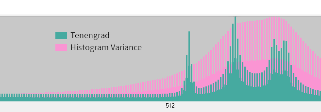
Image Credit: IDS Imaging Development Systems GmbH
Different computing principles mean that each of the three algorithms outlined above differs in terms of the time taken to calculate an image’s sharpness.
For example, the use of sophisticated pixel transformations like Sobel and Laplace filters will result in a higher computing load than a simple standard deviation calculation from a mean gray value.
Analysis of larger regions of interest will rapidly decrease the acquired camera frame rate. Depending on the scene and the requirements of the application in question, it is possible to influence the measurement’s speed and accuracy by opting to use an appropriate algorithm.
The Mean Score and Histogram Deviation methods are more suitable for time-critical calculations on average PC hardware, but the enhanced efficiency afforded by the Tenengrad calculation will often be at the expense of the achievable frame rate when working with larger measurements windows.
Selecting a Region of Interest and Focus Range
In order to speed up calculation time, a sharpness measurement is generally performed in a region of interest that is often referred to as a measurement window.
Larger measurement windows require more computing time and power from the host CPU in order to complete a sharpness calculation.
Set frame rate can also decrease if the calculation time (per image) is too long, so it is advisable to select a measurement window that is as small as possible in order to achieve fast frame rates.
The size and position of the measurement window should be specified so that only the image content to be focused is marked, with one focus plane and, therefore, one maximum focus.
If there are a number of local sharpness maxima in the specified search range, a peak search algorithm is being utilized with a termination condition, the algorithm will terminate the search prematurely once the first clear maximum has been detected.
There are a number of options available to more precisely specify the search for the desired focus level.
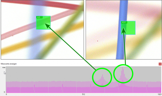
Measurement window and focus range can contain several focus maxima. Image Credit: IDS Imaging Development Systems GmbH
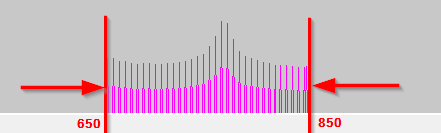
Restricting the Focus Range of the Lens
This solution involves limiting the focus measurements to only the focus range of the lens required for the application.
A small area may be sufficient depending on the depth of field of the lens used and the distance between the lens and the image scene. This solution will also reduce maximum search time because fewer sharpness calculations will be required.
Users unsure of where to set the focus range are advised to display the measured values window and employ a full scan of the entire focus range with a small hysteresis.
Restricting the focus range of the lens. Image Credit: IDS Imaging Development Systems GmbH
Change the Size and Position of the Measurement Window
Only a few clear features are required in order for the algorithms to determine sharpness; for example, a clear edge, small structures, clear gray value scattering. A smaller measurement window will allow focus to be determined faster, with only one image area more clearly in focus.
It is therefore important to make the measurement window as small as possible while keeping this as large as necessary. The more reproducible the image position of the focus objects is in an application, the easier it is to pre-set the size and position of the measurement window.
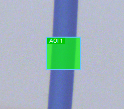
Observe size and position of measurement window. Image Credit: IDS Imaging Development Systems GmbH
Determine Maximum Sharpness
The autofocus function is designed to rapidly determine the focus setting with which the sharpness values in the measurement window of the captured images are greatest.
The uEye software offers several basic peak search algorithms for this purpose, which are suitable depending on the scene (image content) or the user’s speed and quality requirements.
The most reliable (yet slowest) method involves sequentially setting the focus and taking one picture at a time in order to determine its sharpness.
To speed up the search for the optimal sharpness value, a number of random samples are taken according to various strategies. This is done by skipping focus settings first (intervals). Peaks will be located in further runs, are these are then scanned much more closely.
The individual algorithms are able to reduce search time via abort conditions, but this approach does not always lead to optimal results.
The uEye software allows users to select their choice of search strategy. It should be noted that the focus calculation is based on the image content and several measurements are necessary to find an optimum value, so the image content must not change during the search process.
Search Algorithm Characteristics
Golden Ratio Search
This algorithm searches and refines the maximum search by subdividing the search area by the golden ratio. It offers very fast search speeds, even when working with large search areas.
It is possible that the maximum sharpness is skipped during the rough search when using a large search range. This can be addressed by reducing the search range in advance or only using this algorithm with a unimodal sharpness gradient (with only one sharpness maximum).
Hill Climbing Search
This algorithm begins the rough search with a wide range, using a large search interval. It detects a maximum value, which is when the sharpness values no longer increase. The algorithm then aborts searching in the following focus area with the first decrease in sharpness value.
Next, it refines the measurement results in the determined maximum range, doing so in subsequent search runs using smaller search intervals. This search will only abort when the hysteresis is undercut, and while it is faster than Global Search, the first maximum determined may not actually be the global maximum.
It is possible that the maximum sharpness will be skipped during the rough search when using a wide search range. To address this issue, it is advisable to reduce the search range in advance or use only use this algorithm with a unimodal sharpness gradient.
Global Search
This algorithm also commences the rough search in a wide range with a large search interval. A rough search is performed in the whole search area before refining the measurement results in the found maximum range in subsequent search runs, using smaller search intervals.
The algorithm only aborts when the hysteresis is undercut. This approach is faster than Full Scan, but when covering a large search range, maximum sharpness may be skipped during the rough search.
It is recommended to reduce the search range in advance to address this or to only use this approach with a unimodal sharpness gradient.
Full Scan
Full Scan calculates the sharpness values in the entire search range in a single pass without using a search strategy. Here, hysteresis defines the measuring interval.
This algorithm is highly suited to blind searching because it reliably finds the global maximum of sharpness with a small hysteresis.
This search is time-consuming when working with small hysteresis and wide search range, however. In the worst case scenario, 1024 focus values (maximum count of focus settings of the uEye LE AF) will be determined.
Some algorithms are prone to finishing searching too soon or too close to focus settings. The global maximum may not be located if the depth of field in the area of interest is not large enough. In these instances, only a Global Search or Full Scan is likely to be successful.
Maximum Search Accuracy
The hysteresis will determine the minimum step size, at which the search for the maximum sharpness is stopped. This also defines the achievable accuracy of the maximum search. In Full Scan, however, the hysteresis will specify the constant step size used to scan the whole search area.
Typical Focus Camera Applications
The uEye LE AF board level camera series is suitable for any application involving variable object distances when this is used with liquid lens and automatic focus. The camera software also facilitates manual or automatic adjustment of the focus plane, which is very useful when no access to the lens is possible.
In mobile applications like movable robot arms, the small board level camera will focus objects or codes to be read clearly after each robot movement.
The uEye automatic focus system offers a great deal of additional potential when used with image processing functions such as HALCON.
For example, HALCON can calculate a continuously sharp image that clearly depicts an object scene at all focus levels, regardless of the focus setting used. This effectively yields an HDR image related to the focus rather than the exposure (High Dynamic Focus).
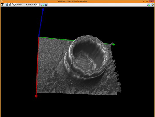
Depth information, calculated from focal values of all focused planes. Image Credit: IDS Imaging Development Systems GmbH
HALCON can scan an object scene on all focal planes, allowing it to calculate depth information (Depth from Focus) on the basis of the sharpness measurements from these images.
This functionality allows the volume of objects to also be determined without a 3D camera, and it is also possible to determine whether objects reside on the same floor.
A standard HALCON installation includes a range of ready-made focus image processing examples that can be used directly with the uEye LE AF.
The IDS Software Suite 4.93 manual includes additional code examples, a detailed description of the focus function and information on its full range of interface parameters.

This information has been sourced, reviewed and adapted from materials provided by IDS Imaging Development Systems GmbH.
For more information on this source, please visit IDS Imaging Development Systems GmbH.