Multiband filters can be categorized into a range of classes. However, these classes all present their own fabrication challenges, which limits the practical outcomes of the thin-film manufacturing process and affects its reliability. Understanding the scientific and industrial applications for multiband filters can help to better equip users with knowledge on the various filter classes and their manufacturing capabilities.
Applications for Multiband Filters
All multiband filters can allow multiple, distinct wavelength regions, that generally range from the ultraviolet (UV) to the mid-wave infrared (MWIR) (or approximately 280 nm to 5 μm), to transmit through the filter and block the bands in between.1 Multiband filters that have this comb-like spectral structure are a subset of hard-coated, dielectric thin-film optical filters. These filters are constructed by depositing alternating layers of materials with varying indices of refraction onto a substrate.
Multiband optical filters are essential to life sciences applications. Multi-bandpass excitation and emission filters have found application in fluorescence microscopy, where they are used with polychroic beamsplitters to enable users to simultaneously detect multiple fluorescent tags in a single sample.
There is growing demand for high-performance multiband filters with extremely high transmission (93–98%), deep blocking (optical density >OD5.5 by measurement and >OD8 by design), and steep transitions between bands (near-vertical slopes approaching <1%) because of the continuously growing advances in the field. New classes of switchable monochromatic LED and laser light sources are just two examples that have driven the increased need for these high-performance multiband filters.
Also driving demand for high-performance multi-notch filters that maintain broadband transmission while simultaneously blocking multiple laser lines are the advances seen in laser fluorescence and Raman spectroscopy applications. The amount of laser light required to elevate a fluorophore into an excited state is much higher than that seen in the returned Raman signal, which is inversely proportional to the fourth power of the excitation wavelength.
In certain cases, this means users must detect a fluorescence marker that is 1012 times smaller than the excitation intensity. As a result, it is essential to block superfluous light in the system in order to keep the emitted signal at the detector from becoming flooded. Flooding can be avoided with deep attenuation (>OD6) at the laser wavelengths. If the notch edges are not steep enough, the signals in proximity to the laser wavelengths will be lost because of the close proximity of the wavelength between modes of excitation and emission.
Numerous other disciplines are now benefiting from the rapid increase of high-performance multiband thin films, including:
- Remote sensing
- Laser blocking
- Semiconductor fabrication
- Industrial monitoring
For example, a dual-band IR filter with low-passband ripple and essentially zero absorption in the water band at ~2.7 μm can be used to monitor climate change (see Fig. 1). Fabricating this filter requires the coating process to be highly stable, because the majority of traditional processes contain some water traces during deposition or they tend to absorb water after coating because of they are porous in nature.
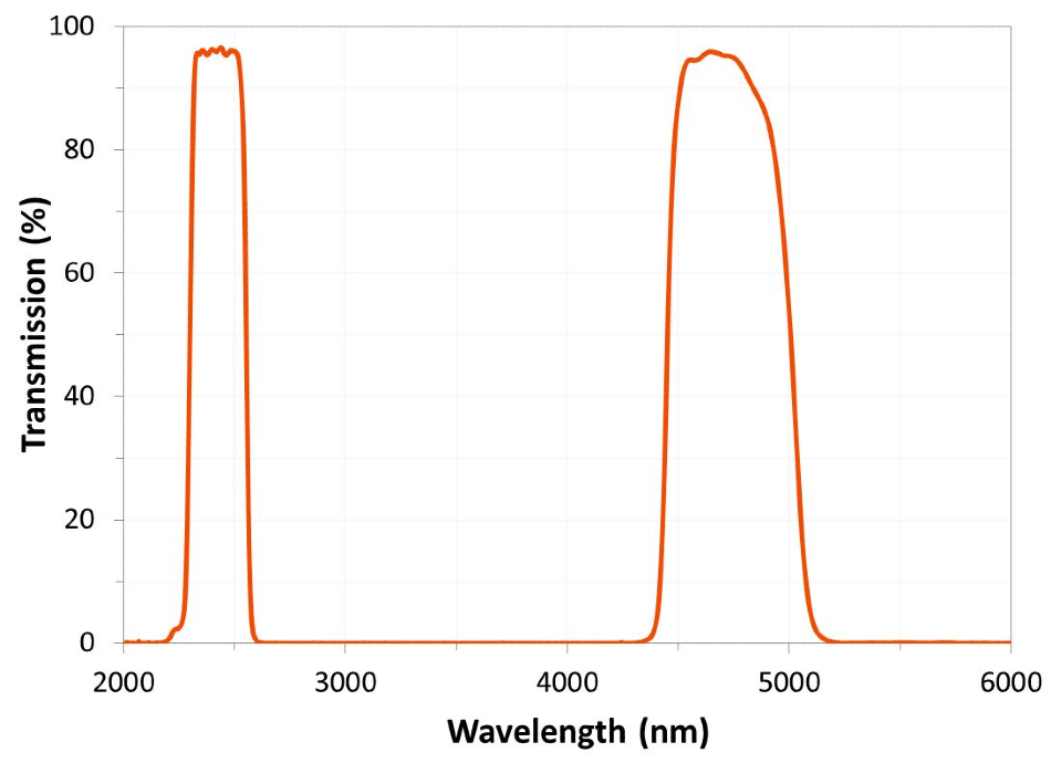
Figure 1. A dual-band IR filter used to monitor climate change exhibits negligible absorption in the 2.7 μm water band and low passband ripple. Image Credit: Alluxa
Multiband performance sees continuous improvements in the number of bands, throughput, blocking levels, and spectral edge steepness. Multiband optical filters now compete with classic single-band filters by delivering equivalent flat-top profiles and deep-OD blocking in series, which allows designers of these optical systems to make them more compact and increase their efficiency.
The design and fabrication of multiband filters is not a trivial factor to consider even for the single band case, and requires designers to have a high level of understanding of the principles of constructive and destructive interference. They must have this deep understanding in conjunction with a sophisticated process to monitor and control material deposition, too.
Multiband filters can be split into five broad classes:
- Wideband
- Narrowband
- Edge dichroic
- Notch
- Filters with arbitrary spectral shapes
However, in increasing the number of bands to filters introduces complications that are unique to each filter class, which require key factors in the manufacturing process to be considered.
Multi-Wideband Filters
Multiband filters with relatively wide bandwidths of 20 to 50 nm are widely used in life science applications, for example in bioimaging systems, which require multiple illumination bands for excitation and emission.
Transmission can average 90–95% within the passband. Average blocking levels range from OD5 to OD6 between bands. Generally, in multiband filters, the transitions between the passband and blocking bands are ~2% of the wavelength, but narrower spectral transitions can be achieved.
Excitation (EX) and emission (EM) channels are fabricated by thin-film deposition methods that have come from interference principles. Although these channels are fabricated separately, they are specified to work together. Transmission and blocking channels need specific placements in multiband EX and EM filters, and they need to be maintained during production. Edge positions define the mid-point transition from high OD blocking to high %T (cut-on) or, conversely, the transition from high transmission to deep OD (cut-off), which establishes boundaries for each channel (see Fig. 2).
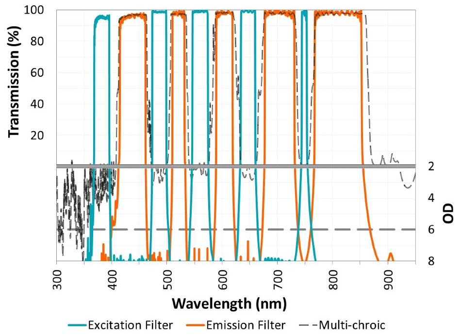
Figure 2. A full-multiband fluorescence filter set is shown, consisting of high-performance pentaband excitation (EX), emission (EM), and polychroic filters. Image Credit: Alluxa
The control and accuracy of the position of edges is critical for each band and for each respective filter in the system. Overlapping in EX/EM bands, or insufficient blocking between bands can lead to unwanted crosstalk in a system, which is an issue that should be considered and addressed in the design phase. This can be done by making sure that the OD level between EX and EM channels is ideally >OD6, although >OD5 in some cases can work sufficiently.
Keeping cut-on/off points tightly controlled can be achieved with precise monitoring methods, in which individual layers of dielectric material are measured and adjusted in real-time as they are deposited with alternating high (H) and low (L) index layers. Correcting layer errors in situ with sophisticated monitoring techniques can be done, which also helps to eliminate manufacturing errors that can commonly occur such as ripple, which is an effect of a mismatch in HL material where there is unwanted variation in transmission levels vs. wavelength.
As more bands are added, a precisely controlled and stable manufacturing process is proved to be crucial in order to maintain sharp and well-defined edges. If the manufacturing process is not controlled, uniformity issues caused by rate drift within a run can mean that adverse wavelength shifts occur, resulting in spectral overlap between the EX and EM channels. This can translate into reduced contrast in the final fluorescence image.
Multi-Narrowband Filters
Narrowband filters transmit wavelength regions that are less than 10 nm wide. As a result, multi-narrowband filters transmit multiple narrow bands in series at the same time. These filters work similarly to multi-wideband filters, but can prove more challenging to produce.
Narrowband designs rely on stacked Fabry-Perot resonant cavities with dielectric reflectors, which comprise quarter-wave-thick layers, spaced apart by cavities that are multiple half-wavelengths across.2 Multi-cavities are used to “square up” the spectral wave shape, which leads to the transmitted light having a flat-topped spectrum when compared with a single-cavity design, which produces a more rounded spectrum.
Making a single-band, multi-cavity filter is challenging for most coating deposition systems. A computer-controlled variation on the turning point method, known as spectral monitoring, is the most effective way of accurately controlling the thickness of depositions for each individual layer.3 The filter is constantly measured during the coating process and variations in thickness are compensated for, and thickness errors that are linked to multiple layers are taken into account. This approach enables remarkably reproducible low-ripple narrowband filters that consistently match theory.
Multi-narrowband filters allow optical designers to analyze the spectrum in arbitrary ways, which gives rise to a huge array of potential applications that are used in conjunction with today’s high-power light sources. For example, Alluxa produces a 10-channel filter that generates a comb of wavelengths in the visible spectrum with flat-topped, high transmission and >OD5 blocking between bands (see Fig. 3). After passing white light through the filter, each individual band can be easily redirected and analyzed independently.
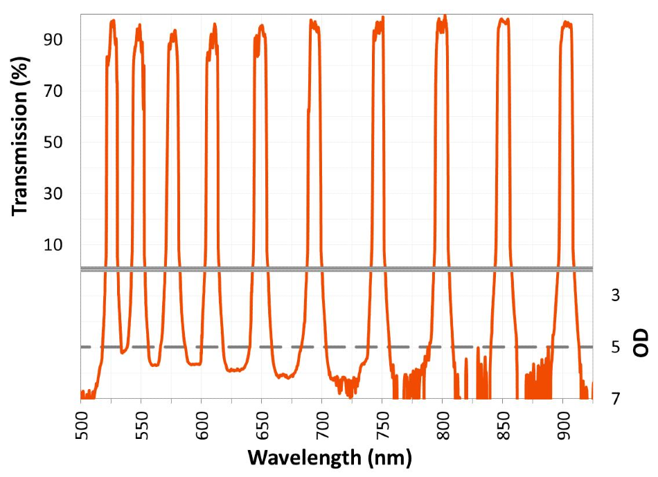
Figure 3. A 10-band multi-narrowband filter fabricated using a multiple design approach. Image Credit: Alluxa
For many standard filters, a measurement with minimal edge distortion and a noise floor of OD4 or OD5 can be taken with a moderate spectral bandwidth (SBW) setting and by using a relatively wide aperture. However, all of the techniques mentioned in this article are not sufficient for measuring and evaluating steep edges, blocking beyond OD6, or ultra-narrow bandpass filters.
Multi-Edge or ‘Polychroic’ Filters
Polychroic filters, which are commonly called beamsplitters, are often used alongside multi-wideband filters in fluorescence systems. Polychroics divide the input spectrum into two beams: one beam in reflection and a second in transmission. They are designed to be used at an angle (usually 45°), although it is possible to use polychroic filters at other angles. These filters are bidirectional, and are used to combine and separate the spectral bands as necessary.
Typically, polychroics are single-sided filters coated with a second surface antireflection film to avoid ghost imaging. Sharp transitions from reflection to transmission and vice versa enhance the contrast of the images in many applications, including fluorescence and multispectral bioimaging. To use polychroic filters in these particular systems, dichroic filters have to have low angle shift and low polarization splitting, and a number of systems also require excellent flatness in both the reflected and transmitted wavefront in order to eliminate any noticeable focal shift that may negatively affect the quality of the image.
In specific cases, these filters require control of phase or group delay dispersion (rather than the transmission amplitude) over distinct passbands. One example is seen in quadchroic beamsplitters, which control the phase of reflected light for all six excitation lasers integrated into a 3D structured illumination microscope (3D-SIM). A final composite image is generated after the excitation light is manipulated into multiple 3D-SIM configurations. Careful attention and design is needed to control both amplitude and phase, but it also necessitates a deposition process capable of producing coatings that align very closely to theory.
Similar to wideband filters, the 50% cut-on/off edge location is critical. As design layers are often non-quarter-wave thicknesses, deposition techniques have to minimize layer errors. For filters that have been designed to work at unusual angles of incidence, the measurement process and evaluation is non-trivial, particularly for more than two transition edges in series. Additionally, substrate thickness and polarization splitting can introduce limitations in measurements, such as deviations of the beam, and translation of the 50% edge, which can affect that evaluation of the spectral properties of the filter.
Multi-Notch Filters
Possessing the inverse spectral profile of multiband filters, multi-notch filters block or reflect discrete wavelength bands of interest rather than transmit them. The shape and design of the filter structure can differ, but overall, these types of filters aim to increase in-band rejection and maximize transmission for out-of-band light.
Multi-notch filters were introduced over 20 years ago, and were primarily designed for applications in human laser protection and machine vision. While multi-notch filters are still used for that purpose, their performance has greatly increased with a wide array of new applications.
For example, 3D cinema uses simple notch filters to divide the visible spectrum into two non-overlapping and offset spectral combs; one for each eye. Conversely, Raman systems require ultra-narrow notch filters to block the laser excitation light and transmit the Raman signal. Surgeons use narrow, color-corrected notch filters to block reflection from the working laser during surgical procedures, while keeping the neutral color appearance image through the filter. The spectral correction features are typically made up of partial or full-notch shapes in the spectrum to balance the CIE white point of the filter in transmission.
Multi-notch filter design comes up against more challenges when the OD level increases and bandwidth narrows, because layer count and complexity increase more or less linearly with the OD level, and inversely with bandwidth. Similar to multi-narrowband filter structure, multi-notch design needs high levels of layer accuracy and control to flatten out-of-band transmission regions and steepen blocking profiles.
When possible, designers aim to capitalize on design harmonics, for example, a 266 nm/532 nm/1064 nm triple notch, to minimize random errors during fabrication. These harmonics provide natural blocking regions. For example, a 1064 nm notch is modified with relative ease to block the 532 nm band as well, simply by reconfiguring the ratio of H and L materials within the repeating thin-film stacks. In doing this, one design gives way to two notches, instead of two notches being constructed independently and then arranged to work within the same design.
Multibands with Arbitrary Shapes
Arbitrary multibands do not fit the classic shape or structure of the filter classes described above. Instead, these filters can use a “target” profile to manipulate incident light into multiple bands with defined transmission variation. Therefore, this creates a highly custom-tailored response curve. For example, a solar filter can shape the output spectrum of a standard light source to match the spectrum of the sun, as illustrated in Fig. 4.
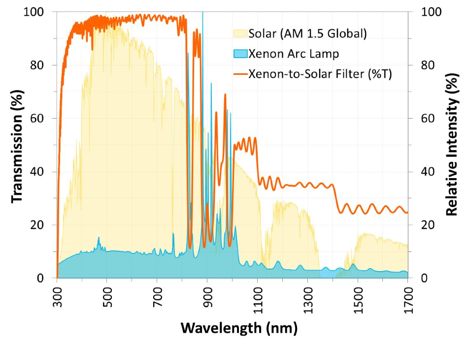
Figure 4. A custom optical filter designed to shape the spectrum of a Xenon arc lamp to that of the sun. Image Credit: Alluxa
These designs require a large amount of computing power when they are being designed. During the fabrication process, they often experience random deposition errors that can affect the target transmission magnitude and location. Generally, manufactured filters achieve spectral shape targets to levels of ±5% or better than theory, although it does depend on the exact profile and features of the curve.
Multiband filters with cutting-edge levels of performance continue to push the boundaries of possibility in optics. As demand continues to increase, thin-film filter manufacturers will carry on engineering innovative ways to fabricate these filters at competitive prices.
Literature Cited
[1] Alluxa engineering staff (2013). Precision Infrared Narrow Bandpass and Dual Bandpass Filters Featuring Low OH-Band Absorption. Alluxa White Paper Series. https://www.alluxa.com/learning-center.
[2] Scobey, M., Egerton, P., and R. Fortenberry (2013). Advanced Plasma Deposition Improves Ultra Narrowband Optical Filters. Alluxa White Paper Series. https://www.alluxa.com/learning-center.
[3] Macleod, H. A., and D. Richmond (1974). The Effect of Errors in the Optical Monitoring of Narrow-band All-dielectric Thin Film Optical Filters. Optica Acta, 21, 6, 429–443.

This information has been sourced, reviewed and adapted from materials provided by Alluxa.
For more information on this source, please visit Alluxa.