The application of augmented and virtual reality (AR/VR) devices is quickly growing in industries that are as diverse as education, gaming, transportation, military, and medicine.
By 2021, the VR/AR headset market is predicted to reach 81.2 million units with a compound annual growth rate (CAGR) of 56.1%, according to the International Data Corporation (IDC).1
Display technology and hardware environments vary massively, and every AR/VR device manufacturer uses a unique approach to integrating displays within these headsets.
This market growth fuels an increasing demand to measure AR, VR, and MR (mixed reality) displays, which are viewed near to the eye, referred to together as near-eye displays (NEDs) (see Fig. 1), using techniques that are adaptable to the geometries of each device and the different display specifications.
.png)
Figure 1. Examples of head-mounted NED designs including immersive headsets and transparent augmented reality glasses.
The growing importance of AR/VR technology calls for control solutions that ensure visual performance. Yet, achieving a quality, seamless visual experience presents a challenge for device manufacturers and designers because of the limitations of measurement systems.
The power of displays viewed as close to the eye as possible, such as those in AR/VR devices, is their capability to supply immersive visual input. Yet defects in the display are also magnified as the images in these displays are magnified to fill the user’s field of view (FOV).
These defects detract from the user experience, not only that, but they can damage a company’s brand image in this increasingly competitive new marketplace. Therefore, effective display testing is a growing necessity.
Radiant’s AR/VR Lens paired with a ProMetric® Imaging Photometer or Colorimeter helps manufacturers ensure display quality, by providing unique optics engineered for measuring NEDs, like those integrated into mixed, virtual, and augmented reality headsets.
The innovative new geometry of the lens design imitates the position, size, and binocular field of view of the human eye. The aperture of the AR/VR Lens is located on the front of the lens, unlike traditional lenses where the aperture is located inside the lens.
This is to permit the imaging system connected to replicate the location of the human eye in an AR/VR device headset and collect the entire FOV available to the user.
This article outlines the challenges of NED measurement, introduces Radiant’s integrated AR/VR Lens solution, and discusses the solution’s benefits for assessing the human visual experience in NED applications.
Challenges of Measuring NEDs
Market trends in AR/VR show a requirement to measure more displays that are:
1) Viewed with a wide field of view (immersive)
2) Viewed within head-mounted devices (goggles, glasses, and headsets)
3) Viewed extremely close up
.jpg)
Figure 2. With the display in a fixed position within AR/VR devices, an extended horizontal FOV is leveraged for an immersive experience.
Displays Viewed with Wide FOV
Images in AR/VR displays are projected over a range of FOVs (depending on the device). With human binocular vision covering approximately a 114-120 ° horizontal FOV, multiple leading commercially available AR/VR NEDs (primarily VR) attain FOVs ranging between 100-120 ° (see Fig. 3).
.jpg)
Figure 3. FOV comparison of VR headset displays. Source: VRGlassesHeadsets.com.2
The wider the FOV of the display, the more problematic it becomes to comprehensively capture all areas of the display utilizing an imaging system for measurement.
Displays in Head-Mounted Devices
Usually, NEDs are integrated within a head-mounted device (HMD), like goggles or a headset. The measurement system must be positioned within the headset hardware at the same position as the human eye to measure a display as seen by a human user wearing such a device (see Fig. 4).
.jpg)
Figure 4. A NED measurement system positioned within the headset at the same location as the human eye can accurately capture the display FOV as it is meant to be seen by the device user.
To capture the full FOV of the display through the viewing aperture of the headset, the measurement system’s entrance pupil (the optical aperture) must be the same as the human pupil position within the headset.
Displays Viewed Close Up
As they are viewed as near as possible to the eye, NED projections are magnified to produce the immersive experience (see Fig. 2). Potential display defects are also magnified at this proximity.
For example, when viewed close up, dead pixels, color and light uniformity issues, line defects, and inconsistencies from eye to eye become more obvious to the user. The closer a display is to the eye, the more crucial display testing is.
Their resolution is another characteristic of displays viewed at this proximity. NEDs must have more pixels per eye to produce visual realism of projections over the display. Yet, this poses a challenge for display measurement as pixel density and high display resolution, in turn, need higher-resolution measurement devices.
Additional Unique Measurement Criteria
Unique image characterization data and analyses is necessary for display testing in AR/VR application demands. For example, color uniformity, and luminance (brightness of the projection) are vital when images are overlaid on top of the surrounding ambient environment (as in AR), or when combining images from eye to eye.
When displays are viewed near to the eye, image clarity and sharpness are crucial, and testing for these characteristics is carried out via an MTF (modulation transfer function) technique.
Quantifying the image distortion caused by the viewing goggles or display FOV is crucial to enhancing spatial image accuracy and projection alignment. An AR/VR measurement solution should incorporate analysis functions for these common criteria, in addition to consistent, repeatable data to ensure device-to-device accuracy.
Measurement Approaches
Emerging AR/VR technologies call for an innovative approach to display testing, including new software algorithms, methodology, and, most importantly, for in-headset measurement, optical geometries.
Many technologies exist which attempt to adhere to the unique testing criteria for AR/VR devices, but they possess noteworthy limitations when it comes to comprehensively addressing all of the measurable AR/VR display characteristics. Some traditional measurement methods are outlined below.
Machine Vision Cameras
The main limitation of machine vision, as seen in Figure 5, is that it is not appropriate for absolute luminance and color measurement. Traditional machine vision systems only gather relative data; they do not supply metrological data to measure absolute luminance or color as visualized by the human eye in an illuminated display.
.jpg)
Figure 5. Machine vision cameras are imaging solutions that locate and measure features using relative data only.
The measurement system should provide photometric values to carry out a true qualification of AR/VR displays as a human user experiences them. Imaging photometers and colorimeters capture chromaticity and luminance values as the human eye perceives them.
This is done by utilizing integrated optical filters that expose specific wavelengths of light to the camera’s image sensor, and this process replicates the human photopic response.
As they capture a total display FOV in a single two-dimensional image to analyze photometric data in a spatial context, photometric imaging systems are commonly utilized for display testing. This context is vital for evaluations of contrast, distortion, uniformity, clarity (MTF), and image position.
A measurement system with high resolution and signal-to-noise ratio is also required for testing pixel-dense displays like NEDs. Machine vision is usually utilized to accomplish extremely quick, repetitive measurement of visual characteristics, which can be identified based on clearly discernible contrast differences.
Therefore, many traditional machine vision systems sacrifice resolution for speed, providing low-resolution sensors that capture a high ratio of image noise compared to the signal they receive. However, display defects can happen at a level of detail as precise as a single display pixel.
If a measurement system is unable to identify a defect in a high-resolution display from one pixel to the next, it may miss defects that would seem obvious to a human viewing the NED.
Systems with high resolution and signal-to-noise ratio (SNR) are vital for measuring displays in near-eye applications with the same precision as the human eye (these systems may include scientific-grade image sensors, cooling, or calibrations to further reduce image noise).
Limited-Resolution Cameras
As discussed, measurement solutions that utilize low-resolution sensors are a bad solution for testing the high-resolution displays employed in near-eye viewing applications. The human eye is one of the highest-resolution “imaging” mechanisms in existence and it is thought to be approximately 576 megapixels (MP).
It is for this reason that low-resolution imaging systems (even photometry-based systems) will never recognize every defect that a human user would notice at the proximity of an AR/VR display. Low-resolution cameras are not good enough to measure the displays utilized in AR/VR devices.
They could miss small defects such as particles, dots, dead pixels, and are incapable of accurate MTF measurement, which shows the NED device’s capability to project images at a particular clarity or sharpness.
Images gathered for analysis must be unaffected by the imaging system’s resolution to acquire MTF measurements with accuracy. Image clarity (MTF) issues of the NED device are isolated by a high-resolution imager.
Standard Optics
A limitation of traditional optical hardware design is that standard optical solutions are not designed for measuring within NED environments (goggles, headsets) from the vantage point of a human user.
For instance, a traditional 35 mm lens has an internal aperture. This aperture position results in occlusion of the full FOV of the display because of obstruction by NED device’s entrance aperture and the lens housing, as seen in Fig 6.
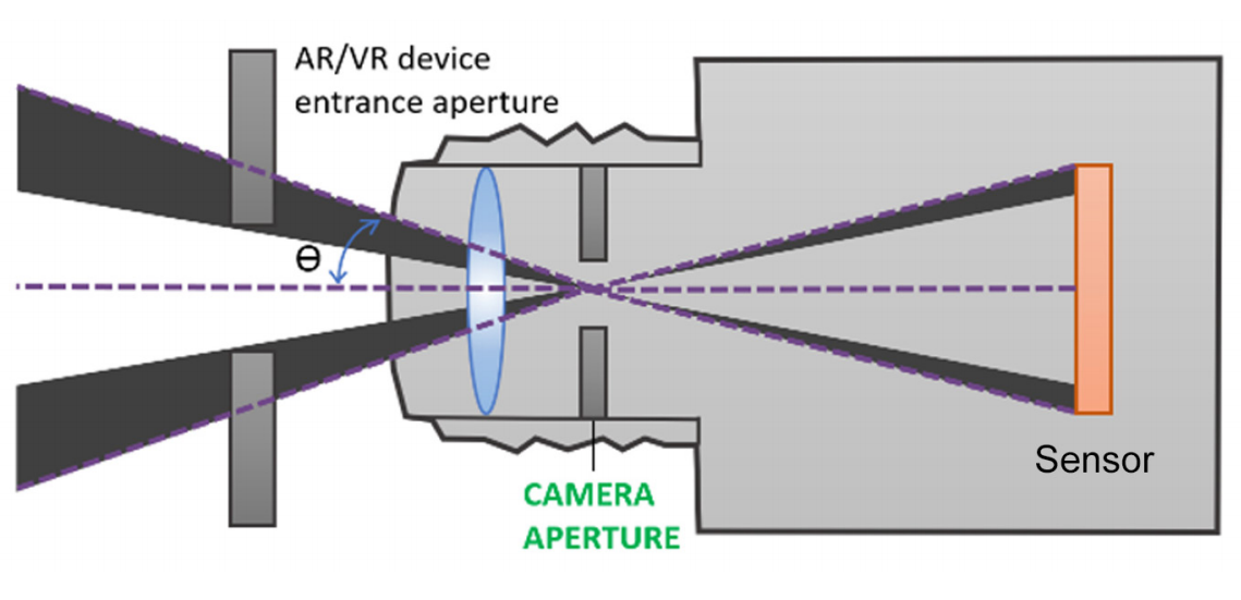
Figure 6. Standard lens with an internal aperture.
Typically, standard lenses are too big to fit inside NED goggles and headsets at the eye position. The width and length of these lenses stop the connected imaging system’s entrance pupil from being located where a human user’s eye would be, impeding the measurement of displays as they are viewed in use.
Custom Optics
Generally, a custom-built optical solution is not suitable for NED display testing within headsets because of minimal scalability to meet future applications, lengthy development time, and expense. Depending on in-house design can also hinder product support through the lifetime of the solution.
Custom Software
Some manufacturers may elect to customize a software component in-house to attain the unique image analysis functions needed for AR/VR display testing.
This has similar downsides to customizing the optical hardware component, including limited product support, minimal scalability for future requirements, more time and expense to implement, and inability to apply software for other display test applications.
Replicating the Human Visual Experience
The standard for optical performance measurement of NEDs should be supplied by human visual perception of display quality. A NED measurement solution should address the scope of display characteristics that can be seen, as with the human eye.
Measuring a display that is integrated within a head-mounted or immersive system is dependent on accessing the display at the appropriate visual position to see the full FOV which is meant to be viewed by the human user. To replicate human vision for NED measurement, there are several vital elements that must be considered by the display test equipment.
Photometric Measurement
The appearance of light and color is the most vital element to the visual quality of any display. As they are engineered with special tristimulus filters (see Fig. 7) that mimic the response of the human eye to different wavelengths of light (the photopic response curve), imaging photometers and colorimeters are best-suited to assess visual display qualities.
.jpg)
Figure 7. Imaging photometers and colorimeters capture luminance and chromaticity values as they are perceived by the human eye, using integrated filters to expose each wavelength of light at a different duration to the image sensor to replicate the human photopic response.
A NED measurement system should employ photometric technology via filters to evaluate light values as the human eye receives them.
Full Field of View
The user should have visual access to the entire FOV projected by the display within the NED headset, and so may be aware of defects at any point on display. Imaging photometers and colorimeters only require a single image to capture the complete display.
An imaging system can see all of the details in a single view at once, like the human eye. It is able to capture a wide-FOV display even as it is viewed close up, via wide-FOV optics that simulate human binocular vision. Therefore, for the most accurate and comprehensive NED measurement, photometric imaging systems paired with wide-FOV optics are recommended.
High-Resolution AR/VR displays are supposed to be viewed very near to the eye, which is a high-precision imager itself. So, NEDs are some of the highest-resolution displays, fitting the most pixels in the smallest form factor for a seamless visual experience of images close up.
The system that is utilized to assess an integrated AR/VR display should have sufficient resolution to gather all of the details in pixel-dense displays, which may be visible to the human eye at close range.
Due to the sufficient resolution of the imaging system’s sensor, each display pixel may be imaged over multiple sensor pixels, allowing pixel-level defect detection, as seen in Figure 8).
.jpg)
Figure 8. The top image shows the raw image captured by a high-resolution photometric imager. On the bottom, an analysis has been applied to detect tiny pixel-level defects. Close-up viewing in the AR/VR headset may make such defects apparent to the human eye.
Aperture
Positioning the measurement device to observe the entire display FOV beyond the goggles is one of the biggest challenges in measuring near-eye displays within headsets.
Tests can be performed to assess any defects that may be visible to the user during the operation of the device if the measurement system can attain an image of the full display FOV as the user sees it. The challenge is that the human eye is at a very specific position within AR/VR headsets.
A display measurement system that can replicate the position, size and FOV of human vision within the headset is crucial for capturing an image of the display for evaluating all qualities that the user may see.
Unique optical parameters that allow imaging systems to gather the full visible FOV include the lens aperture position and geometry. In an optical system, like the lens on a camera, the aperture or “entrance pupil” is the initial plane where light is received into the lens. A similar point is found in the pupil of the human eye.
Aperture Size
For several reasons, replicating the human entrance pupil in NED measurement systems by achieving the appropriate aperture size is important:
1. An aperture that replicates the size of the human entrance pupil captures equivalent light (equivalent detail) of the display as the human eye.
2. If the measurement system aperture is bigger than the human pupil size, the imaged display looks to possess more aberrations than the human would see. (Display qualification may give false negatives.)
3. The imaged display appears sharper, with fewer/less severe aberrations than the human sees if the measurement system aperture is smaller than the human pupil size. (Display qualification may yield false positives.)
Replicating the size of the human entrance pupil allows the imaging system to capture images equivalent in detail and clarity to those viewed by the human eye and make the same assessment of quality.
Aperture Position
A vital objective for integrated NED measurement is simulating the human eye position within AR/VR headsets. A traditional 35 mm lens has an internal aperture, which is unable to capture the full FOV of the display because of the NED device hardware (the edges of the device’s entrance aperture) and obstruction by the lens housing (see Fig. 9).
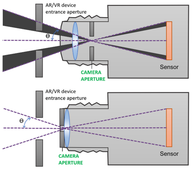
Figure 9. NED measurement requires a unique optical design that positions the camera aperture at the front of the lens, at the same location as the human eye, enabling visualization of the complete FOV of displays as viewed through headsets or goggles.
Optical components that are designed with the aperture in front of the lens reproduce the intended position of the human eye inside the headset. An imaging system with aperture at the front of the lens can capture the full display FOV when combined with wide-FOV optics and can test for all visible characteristics that will be observed by the human eye.
As seen in Fig. 10, this effect is like viewing a scene through a knothole in a fence, when the eye is positioned at the hole, the full FOV can be seen beyond the fence. The view becomes occluded by the edges of the fence as the eye moves away from the hole.
.jpg)
Figure 10. “Knot-hole” example: Top, the entrance pupil is far from the opening (knot hole), providing a limited view of the image. Bottom, the entrance pupil is at the opening providing a fuller view
Radiant AR/VR Measurement Solution
To address the unique challenges of qualifying integrated NEDs under the same conditions as they are visualized by human users, Radiant developed an AR/VR Lens. The AR/VR Lens is designed to be combined with high-resolution imaging photometers and colorimeters (16-megapixels and higher) (see Fig. 11).
.jpg)
Figure 11. The Radiant AR/VR Display Test Solution includes (left to right): AR/VR Lens, ProMetric® Imaging Colorimeter or Photometer, and TrueTest™ Software with optional TT-ARVR™ module.
The measurement system can assess the complete display FOV at once by capturing displays at this detail, with the precision to capture any defects which may be noticeable to the human eye.
In-Headset Display Measurement
Radiant’s AR/VR display test solution is designed specifically for in-headset display measurement. The lens’s ability to replicate the FOV and entrance pupil of human vision is what separates the AR/VR Lens from other optical components.
.jpg)
Figure 12. Radiant’s AR/VR Lens replicates the human eye position in headsets for wide-FOV NED testing.
The AR/VR Lens product specifications include:
1. Aperture (entrance pupil) located at the front of the lens.
2. 3.6 mm aperture size. In bright light, the average pupil will contract to 1.5 mm in diameter and dilate to 8 mm in diameter in darkness. Radiant uses 3.6 mm for two reasons: 1) it is in the mid-range of pupil dilation; 2) the 3.6 mm aperture permits a high MTF for the lens.
3. Wide FOV to 120° (±60°) horizontal.
Importance of Calibration
To ensure the most accurate images for absolute light and color analysis, each Radiant AR/VR camera/lens system is factory calibrated. Calibration processes include factory distortion calibration to eliminate lensing effects of the wide-FOV lens, providing accurate spatial analysis of the display by the camera software.
The image captured by the lens may look distorted when measuring displays with a wide-FOV lens (see Fig. 13). This is because the AR/VR solution utilizes a fisheye lens, so an uncalibrated image shows barrel distortion. Radiant’s camera/lens solution is calibrated to process out distortion effects before performing display tests.
.jpg)
Figure 13. Top, an image captured by an uncalibrated wide-FOV system; bottom, image captured by a system with distortion calibration applied.
This ensures the accuracy of spatial measurements and can identify defects where they appear on the display. Solution Software Radiant TrueTest™ Automated Visual Inspection Software applies analyses to every image captured via Radiant’s AR/VR measurement solution.
A suite of display tests is included in this platform, with standard tests for contrast, uniformity, luminance, chromaticity, and defects like lines and dead pixels. Unique tests for AR/VR projections are also available in the pre-configured TT-ARVR™ software module (see Table 1).
Table 1. Display tests in Radiant TT-ARVR™ software module.
| TT-ARVR™ Software Module Tests |
| • Uniformity |
• Points of Interest |
| • Line Defects |
• MTF Slant Edge |
| • Particle Defects |
• MTF Line Pair |
| • ANSI Brightness |
• Distortion |
| • Sequential Contrast |
• Focus Uniformity |
| • Checkerboard Contrast |
• Pattern Mura |
| • Chromaticity |
• Field of View (Device FOV) |
Figures 14-16 show some examples of TT-ARVR software analyses. These analyses are carried out on the AR/VR display to test the manufacturing specifications of the AR/VR device.
To help consumers to evaluate the device and compare it with competitive products, they can also be published for consumer use (for instance, on an AR/VR headset specification sheet).
Uniformity analysis (see Fig. 14) is used to establish areas of high or low luminance across the display, which may show a defect in the display. This analysis can also be utilized to characterize the uniformity against design specifications.
.jpg)
Figure 14. Uniformity analysis (shown in false color) characterizes display quality.
As seen in Fig. 15, a checkerboard contrast analysis is carried out by projecting a checkerboard pattern on display within the AR/VR headset.
.jpg)
Figure 15. Checkerboard contrast analysis evaluates the contrast ratio of the display.
After the pattern is imaged using the AR/VR test system, the checkerboard contrast test assesses luminance levels in the image to establish the display system’s capability to project distinct dark and light values, a performance parameter which can be demonstrated on a specification sheet.
As seen in Fig. 16, A Field of View test calculates the actual field of view of the display as imaged within the headset, ensuring that the vertical, horizontal, and diagonal dimensions are accurate to design specifications. These measurements may also be reported on a specification sheet for an AR/VR headset.
.jpg)
Figure 16. Field of view analysis measures the display FOV within the NED device.
Conclusion
New display integration environments, such as AR/VR and other head-mounted devices, mean that designers and manufacturers must implement effective techniques to test the optical quality of displays, which are viewed from a fixed position, close-up, within headset hardware.
Standard display measurement equipment does not have the optical specifications to capture displays within headsets to assess the complete visible FOV as seen by the human user.
Radiant’s AR/VR display test solution is the only measurement system that is commercially available, with unique optical components to replicate the human pupil position and size within AR/VR goggles and headsets to capture a display FOV to 120° horizontal.
The system provides the high resolution and efficiency that is necessary for AR/VR device makers, employing a compact camera/lens solution to capture all details visible across the NED in a single image to assess the human visual experience quickly.
References and Further Reading
- International Data Corporation (IDC). (2017, March). IDC’s Worldwide AR/VR Headset Tracker Taxonomy, 2017.
- VRGlassesHeadsets. (2017, March). VR Headset Comparisons: Field of view. The Top VR Headsets Compared.
This information has been sourced, reviewed and adapted from materials provided by Radiant Vision Systems.
For more information on this source, please visit Radiant Vision Systems.