This article demonstrates how to use the Zurich Instruments MFLI, a 500 kHz Lock-in Amplifier, for the purpose of controlling, measuring, and stabilizing the relative distance of two interferometer paths to sub-wavelengths with precision over several wavelengths.
Through the introduction of a phase modulation on one of the interferometer arms, a signal is generated to show the relative displacement continuously and linearly. This signal is then managed by an internal PID controller to make the relative path length stable to an adaptable setpoint.
Motivation
The relative phase difference between the two paths of light propagation is accurately measured by optical interferometers.
They can be applied in the control and detection of changes in relative optical path length of two interferometer arms to a fraction of the light wavelength as used in, for example, quantitative phase imaging [1].
The Michelson-Morley scheme of interferometry is outlined in Figure 1, but different configurations, for example Mach-Zehnder, are also frequently used. Both pathways may experience small relative changes of refractive index, which can be the outcome of changes in pressure or air temperature, will create a large measurable signal.
One limitation of this high sensitivity is that very slight fluctuations, for example, those introduced by varying temperature gradients or mechanical noise, can cause tiny mirror displacements and systematic measurement errors as a result.
Continuous measurement and active stabilization of the relative interferometer phase angle can help to correct these error sources. However, the use of the relative phase angle as a direct input for a feedback system restricts the control range to less than π/2 or a quarter of wavelength, along with further disadvantages.
This article presents an innovative technique developed in the second reference [2], based on the work in reference [3] which offers the following advantages:
- Covering an arbitrary large range of displacement
- Working at relative phase angles that are arbitrary
- Operation controlled manually and by computer
- Simple to set up and monitor
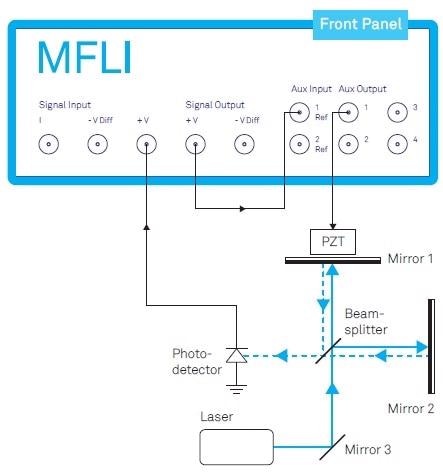
Figure 1. Michelson-Morley interferometer actively stabilized by a closed-loop system employing the MFLI Lock-in Amplifier from Zurich Instruments. The Auxiliary Output enables both a controlling offset and a modulating signal for the piezoelectric transducer (PZT). The external loop-back from the Signal Output to the Auxiliary Input is needed to create the continuous and linearized error signal for PID control (see text).
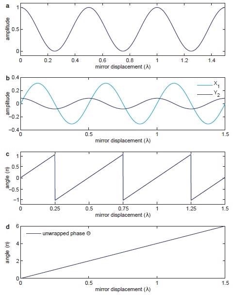
Figure 2. (a) portrays the sinusoidal signal discerned by the photodetector over the relative displacement between mirrors 1 and 2. (b) outlines the signals X1 and Y2 demodulated at Ω and 2Ω. (c) demonstrates the phase angle between the normalized X1 and Y2 components provided in Equation 5. (d) shows the unwrapped version of the same phase in (c) used by the PID controller to drive the PZT.
Description
In the example given in Figure 1, the light intensity I distinguished by the photodetector is outlined by Equation 1.
Equation 1: 
In Equation 1, I0 is the intensity of the laser light at wavelength λ and the phase difference between the interferometer’s two arms is defined by φ.
Figure 2(a) outlines the photodetector signal discussed in Equation 1. It portrays two limitations of detecting the mirror displacement by the phase φ with the photodetector signal.
The first challenge is the discrepancy in sensitivity of the extrema of the curve and the points of maximum scope. The second challenge is to remove the uncertainty resulting from the photodetector signal I as a non-monotone function of φ.
It is impossible to know if the displacement is constantly going in the same direction or if it is going through a turning point when reading the photodetector voltage at extrema points.
Each of these limitations can be solved through the introduction of a phase modulation to one beam path such as by using a sinusoidal voltage of frequency Ω to the piezoelectric transducer, which is managing the relative path difference. Such a phase modulation is outlined by Equation 2.
Equation 2: 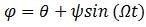
In Equation 2, ψ signifies the depth of modulation and  is the first phase offer due to the length difference ∆L between the arms of the interferometer.
The replacement of Equation 2 for Equation 1’s φ creates a phase-modulated signal consisting of higher harmonics Ω. Through the use of the Jacobi-Anger expansion, the first and second harmonics, I1 and I2, are expressed in regard to Bessel functions J1 and J2 at the modulation depth ψ as outlined in Equation 3(a) and (b).
Equation 3(a): 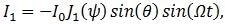
Equation 3(b): 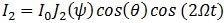
Equation 4(a): 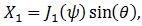
Equation 4(b): 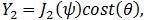
In these equations, the components of Equation 4(a) and (b) look similar to the form of the first and second derivatives of the initial fringe pattern. Figure 3 shows how the slowly-varying signal components X1 and Y2, demonstrated in Figure 2(b), are taken away from the initial photodetector signal using demodulation at the frequencies Ω and 2Ω.
It is important that both components of X1 and Y2 perform with exactly the same strength in order to linearize the response signal. This is ensured by the adjustment of the modulation depth to ψ=2.63 rad where J1(ψ) and J2(ψ) are equal, or by exhibiting the correction factors J1 and J2, as shown in Figure 3.
In each of the alternatives, the resulting parametric plot of both signals should show a circle, rather than an ellipse. In this respect, the phase offset θ is determined by Equation 5.
Equation 5: 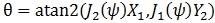
It is a required observation that the function ‘atan2’ is used to choose without ambiguity the phase within a range  from the two arguments. Figure 2(c) shows the outcome of this when compared to the initial photodetector signal.
A phase unwrap is performed to prolong the accessible phase range from the ‘atan2’ operation to an infinite scale as a last effort to achieve a monotonic function of displacement between the arms. The consequent unwrapped phase signal by the relative displacement in units of wavelengths is shown in Figure 2(d).
This signal is now able to be utilized by a PID controller to provide feedback to the PZT as an offset voltage to control the relative lengths of the paths of the interferometer and keep the phase at precisely the determined setpoint of the PID controller.
The residual error signal of the closed-loop controller then gives a direct measurement of the unintended and projected disturbances of the setup.
An important part of this setup is the modulation in one of the interferometer arms. This evidently brings light to the weakness that the stabilization is merely average and is not absolute.
However, for pulsed laser studies where the stabilization is performed with a CW laser, the correct synchronization with the repetition rate of the pulsed laser will correct this problem.
Implementation
The mechanical resonance frequency of Figure 1’s piezo-mirror assembly when used is a few ten kHz at its maximum, which presents an upper limit to the loop filter bandwidth and the speed of modulation.
The MFLI is able to handle modulation bandwidths of as high as 200 kHz, restricted by the Auxiliary Output bandwidth, whereas the bandwidth of the photodetector can go up to 5 MHz.
The maximum loop filter bandwidth depends on the setup features and can go up to 50 kHz. To arrange the setup shown in Figure 3, the MFLI must be equipped with the MF-MD Multi-demodulation and the MF-PID Quad PID/PLL Controller selections.
Figure 4 demonstrates the method utilized to apply the correction coefficients J1(ψ) and J2(ψ) and to choose the phase between the output of two separate demodulators.
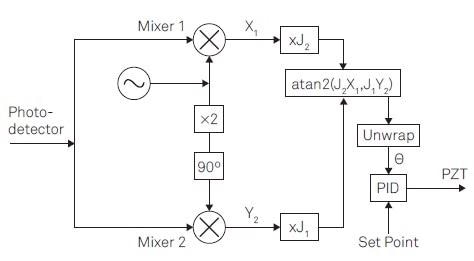
Figure 3. Linear phase control for interferometer stabilization contains the following steps: (1) Offer a reference signal at Ω to apply a phase modulation. (2) Apply lock-in detection to the photodetector signal to acquire the demodulation signals X1 and Y2 at the modulation frequency Ω and its 2nd harmonic. (3) Apply correction factors J1 and J2. (4) Discover the phase θ by atan2(J2X1; J1Y2) (5) Unwrap the phase θ. (6) Apply PID controller to give feedback.
The reference signal at frequency Ω is created in the path of demodulator (Demod) 4 and is directed through the Auxiliary Output to drive the PZT.
The photodetector signal, which includes multiple harmonics of Ω as a consequence of the phase modulation, is received at the Signal Input and demodulated at Ω by Demod 1 to collect X1 and 2Ω by Demod 2 to gain Y2, as shown in Figure 4.
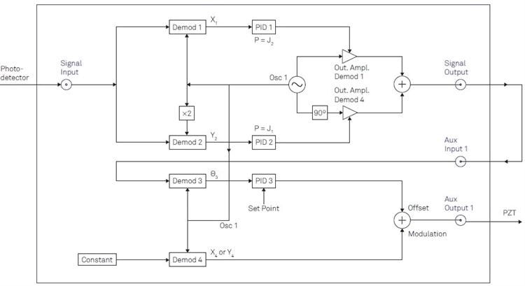
Figure 4. Comprehensive outline of the instrument configuration for implementation in the LabOne user interface. In total, four demodulators (Demods) of the instruments are needed. Two PID controllers are employed as proportionate functions to apply the Bessel coefficients. The third PID controller is utilized to propel the offset signal managing the mirror displacement.
The correction factors J1(ψ) and J2(ψ) are applied to the demodulated signals X1 and Y2 employing the PID controllers 1 and 2 in their balanced mode, meaning that I and D parts are fixed to zero.
The PID output will then change the amplitude of a sine and cosine wave at Ω through the path of Desmod 1 and 4. The consequent signal available at the Signal Output is shown in Equation 6.
Equation 6:
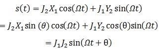
Equation 6 explains that the phase difference θ, due to the length differences between the two arms of the interferometer, is now able to be extracted by demodulating s(t) at frequency Ω.
To perform this, the Signal Output is looped back to the Auxiliary Input and demodulates the signal by using Demod 3, as shown in Figure 4.
Figure 2(c) and Equation 5 demonstrate the phase extracted by Demod 3. The phase signal is consequently employed as an input for PID 3, which unwraps the phase before the signal is compared to the setpoint.
The signal is added to the reference signal in the Auxiliary Output connected to the PZT to seal the loop once it has passed through the PID controller.
To properly set this up, the control software LabOne® by Zurich Instruments provides a web-based operator interface with multiple efficient tools for consistent analysis. For example, it is possible to characterize the transfer function of the PZT-mirror assembly by recording a Bode plot utilizing the Parametric Sweeper tool.
An estimated indication of the maximum loop filter bandwidth is the frequency where the phase nears ±90° estimated. A user could demonstrate the signals X1 and Y2 in the integrated FFT Spectrum Analyzer to evaluate the signal dynamics after this.
Once an accurate estimate for the desired loop filter bandwidth is established, the gain parameters for PID 3 are simply capable of being determined from the PID Adviser and consequently iteratively refined.
This entire process can also be automated by using any of the LabOne APIs, provided for MATLAB®, LabVIEW®, Python, .NET, and C, to integrate it in an available control environment.
Quick Modulation
Setups requiring high-speed modulators, such as electro-optical modulators (EOM) or accustom-optical modulators (AOM), are able to work at modulation frequencies of several hundred MHz.
This enables higher loop-filter bandwidths to remove unwanted noise components at elevated frequencies. In these cases, Zurich Instruments UHFL, a 600 MHz Lock-in Amplifier, is the preferred choice, which can also be equipped with four PID controllers to use the scheme outlined above.
The major difference in implementation with the UHFLI is its ability to generate the reference signal at a Signal Output rather than an Auxiliary Output.
It takes away the restriction of the modulation frequency to the bandwidth of the Auxiliary Output, so that the reference signal is able to cover the total frequency range of the instrument, in this case as high as 600 MHz.
The alternate Signal Output is employed for the signal s(t) covering the phase information, which once again is looped back to one of the Signal Inputs to extricate its phase. The alternate Signal Input controls the photodetector signal to demodulate it at the first and second harmonics.
The UHF-MF Multi-frequency selection is required to easily choose multiple demodulators and assign them to adequate signals and change their phase and frequency.
Three of the four PID controllers provided by the UHF-PID Quad PID/PLL Controller choice are further required to utilize the correction factors and to generate the control signal for mirror displacement.
Conclusion
Through the MFLI and UHFLI, Zurich Instruments provide single-instrument solutions for control of modulation frequencies of up to 600 MHz and interferometer stabilization.
The method demonstrated in this article can be quickly and easily implemented with the LabOne operator interface, which has multiple essential tools to monitor and characterize the setup of the investigation. LabOne APIs also provide complete computer control.
References and Further Reading
[1] H. Iwai, C. Fang-Yen, G. Popescu, A. Wax, K. Badizadegan, R. R. Dasari, and M. S. Feld. Quantitative phase imaging using actively stabilized phase-shifting low-coherence interferometry. Opt. Lett., 29(20):2399–2401, 2004.
[2] A. A. Freschi and J. Frejlich. Adjustable phase control in stabilized interferometry. Opt. Lett., 20(6):635–637, 1995.
[3] U. Minoni, E. Sardini, E. Gelmini, F. Docchio, and D. Marioli. Adjustable phase control in stabilized interferometry. Rev. Sci. Instrum., 62:2579, 1991.

This information has been sourced, reviewed and adapted from materials provided by Zurich Instruments AG.
For more information on this source, please visit Zurich Instruments AG.