The surface profiling by an optical testing interferometer involves interference signal interpretation at each image pixel for interference phase estimation at each of these points. The estimated interference phase is then related to surface height. In most of the devices, at least three different intensity images with added relative phase shifts are involved in the phase estimation. Today’s dominant technique uses proven phase shifting interferometry (PSI) to impart the phase shifts in sequence over time, often mechanically.
In the Fizeau interferometer configuration, the PSI method is totally common path in the limit of short interferometer cavities, thus offering a high degree of self-correction for optical imperfections such as polarization effects and retrace errors.
Alternative Technique to the Time-Based PSI Method
Instantaneous interferometers can be a substitute for the time-based PSI technique as they impart phase shifts onto the interference signal that can be measured at the same instant in time or within the duration of a single shuttered camera frame, for instance, 1 msec.
This method holds potential to capture dynamically changing events thanks to its environmental insensitivity.
It is necessary to encode the interferometer’s reference and measurement beams for manipulating their relative phase, which, in turn, allows the concurrent introduction of multiple phase shifts. One approach is the isolation of the reference and measurement beams along varying spatial paths, as in the case of a Twyman Green, or the introduction of a tilt angle of the reference beam regarding to the measurement beam.
The latter is possible in a modified Fizeau. Another method involves the use of two interferometers in tandem, of which one has geometrically separable reference and measurement beams and the second equipment has the test object. The encoding relates the measurement beam with the test object through coherence matching of the two cavities.
Besides encoding the reference and measurement beams, a detection technique is required for capturing three or more phase-shifted intensity signals concurrently for every pixel in the field of view. There are several methods available, of which a technique for spatial phase shifting on a single camera utilizes a special camera mask to create phase shifts local to individual pixels through the use of polarization-encoded reference and measurement beams.
Need for an Efficient Solution
For geometrically encoded systems, the paths followed by the reference and measurement beams through the optical system are not the same. Dissimilar paths might be there in at least one of the tandem interferometers for the coupled cavity systems.
On the other hand, for polarized interferometers, the polarizing properties of optical components that cause offsets and cyclic errors need to be addressed. Hence, several factors need to be considered for selecting an appropriate instantaneous interferometer solution, such as the ability to calibrate and compensate for errors, and the associated cost and complexity.
Spatial Carrier Fringe Solution
Considering its potential simplicity and low price, as well as its proven performance on high-precision devices, it is necessary to improve the classical method of spatial carrier fringes for instantaneous interferometry. Non-common path errors are the major problem for instantaneous interferometry.
To tackle this issue, Zygo has devised in-situ calibration and compensation for predictable and repeatable correction to below 5-nm PV (or 0.008λ PV) for static errors caused by spatially non-common path geometries, without calibrating artifacts. Spatial carrier fringes set to ½ Nyquist in X and Y, in conjunction with a traditional Fizeau interferometer and accurate compensation, deliver total measurement uncertainty, which is constant with uncompensated temporal PSI acquisition.
An outstanding correlation between sequential measurements taken by a spatial carrier and traditional PSI is shown in Figure 1. A pixel-by-pixel difference of the two maps delivers a ΔPV < λ/50.
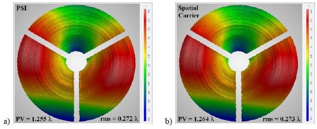
Figure 1. Diamond-turned parabolic surface tested in a classic null configuration with collimated wavefront reflected from the parabola towards a reference sphere (held by a “spider”): (a) with 13-bucket PSI; (b) with a modern, optimized spatial carrier algorithm. A pixel-by-pixel difference of the two maps, measured sequentially, yields a ΔPV < λ/50.
Instantaneous interferometry acquires, processes, and averages phase in the presence of turbulence and vibration. Moreover, it is capable of viewing, capturing and analyzing dynamic events in real time, as shown in Figure 2.
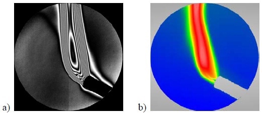
Figure 2. Single-frame capture of dynamic thermal gradients viewed (a) as interference fringes; (b) as a processed 3-dimensional map. These results are viewed live through high-speed data processing to facilitate interpretation of rapidly-changing, dynamic events.
Lateral resolution is significant to researchers who have interest in measuring more than image error. The lateral resolution capability of an optimized carrier fringe algorithm is illustrated in Figure 3.
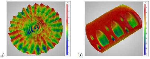
Figure 3. 3D height maps demonstrating lateral resolution capabilities on a 1000x1000 detector array using an optimized spatial carrier algorithm: (a) an optical flat showing mid-spatial frequency errors generated by small-tool polishing; (b) a “spot” block used to characterize the polishing footprint for deterministic polishing correction.
Conclusion
A spatial carrier implementation is fully compatible with a Fizeau interferometer that is configured for traditional PSI, thus providing more options in measurement technique.
ZYGO's Verifire™ HD Interferometer & Nomad™ Optical Profiler Demos at Photonics West 2016
Instantaneous interferometry facilitates high-resolution metrology where conventional PSI measurements cannot be performed due to separated metrology platforms, environmental noise and/or cavity length. An optimized spatial carrier fringe solution is suitable for these applications, and is lower in cost and complexity when compared to other methods.

This information has been sourced, reviewed and adapted from materials provided by Zygo Corporation.
For more information on this source, please visit Zygo Corporation.