Various optical companies employ an interferometer and slide mechanism to perform noncontact and precise radius measurement. Interferometry has long been used for measuring the radius of curvature, as it provides precise measurement of 0.01%. Actually, with proper implementation, this precision can be further improved to 0.001%. This application note explores the control and correction of optical and optomechanical errors.
Radius measurement
Radius measurement is quite susceptible to site implementation and method. Control of environmental factors, vigilant measurement process, and appropriate tooling design are important to obtain the required precision, which is provided by this measurement method.
The radius of a sphere refers to the distance from the spherical surface, or to the related center of curvature. Using a point source interferometer, both these locations can be viewed, thus creating a converging wavefront such as a Twyman-Green or Fizeau, as shown in the figure below.
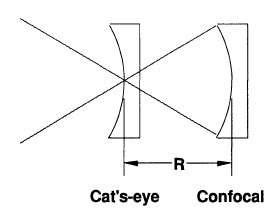
Figure 1. Radius measurement geometry, showing cat's-eye and confocal measurement positions.
At the ''cat's-eye'' location, the interferometer beam meets to a point on the spherical surface. A nulled fringe pattern specifies that the point focus is at the sphere’s surface. At the confocal position, a nulled fringe pattern specifies that the interferometer point focus is coincident with the curvature’s surface center. By calculating the distance of the part shifted between these null positions, that is from cat's-eye point to confocal, the radius of curvature is measured. This distance can be precisely calculated when the measurement axis meets the surface center of curvature and the cat's eye point. The major errors, like Abbé errors, are usually 10 to 100 pm and can be almost eliminated by employing a distance-measuring interferometer. The remaining errors, such as axial alignment errors and cavity null errors, are measured and corrected. Other errors like tooling and environmental errors are also cataloged and measured.
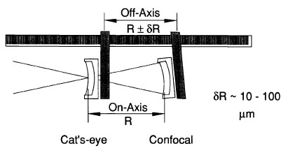
Figure 2. Abbé errors are caused by measuring along an axis displaced from the axis of motion.
Equipment for Radius Measurement
The radius measurement equipment includes a DMI configured as a linear interferometer, a phase-measuring point source interferometer with a transmission sphere or diverger lens, and a rail/guide assembly with a mount with five axes of motion to grip the surface under test. This mount is shifted along a rail/guide.
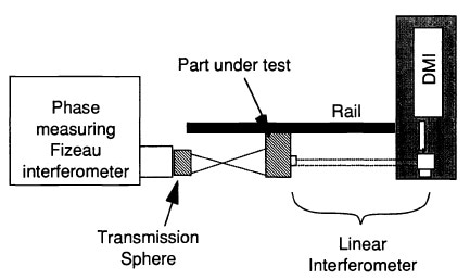
Figure 3. Interferometric radius measurement system including phasemeasuring Fizeau interferometer with transmission sphere, DM1 with linear inter-terometer, five-axes mount, and guide.
An advantage of the distance-measuring interferometer is that the rail specifications are considerately relaxed. The interferometer‘s moving corner cube is attached to the part mount so that its tip remains on the part axis.
Two possible implementations are available, one is z tracking wherein the moving cube is positioned only to the z adjustment of the mount and hence cannot track tip/tilt functions or lateral direction.
The other is fully tracking wherein the moving cube is positioned at the part and thus can track tip/tilt or lateral motion of the part, which lies along the axis of the distance-measuring interferometer. In the z tracking implementation, the signal of the distance-measuring interferometer is not lost during lateral motion of the part.
ZYGO's Verifire™ HD Interferometer & Nomad™ Optical Profiler Demos at Photonics West 2016
Sources of Errors
Axial Alignment Errors
For radius measurement, three axes are important and they include d (DM1 beam), p (part axis) and r (axis of motion). The angles that exist between these axes are α (p,d), β (p,r) and γ (r,d), as shown in the figure below.
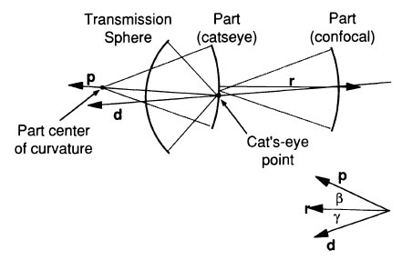
Figure 4. Relevant axes for radius measurement, p, r, and d.
The net motion along the part axis (p) is R, which happens to be the surface radius. For complete tracking configuration, the error relies only on the alignment of the part axis to the distance-measuring interferometer. In case of z-tracking configuration, depending on the part alignment β and the system alignment γ, the error becomes compound.
In order to obtain precise measurement, the net motion of surface between the confocal and cat's-eye positions should be in the direction of the part axis and the distance-measuring must calculate all motion in this same direction, that is the d, p and r axes must remain parallel.
Null Cavity Errors
The position error induced by a nonnulled cavity is obtained from the sag equation for a sphere. Usually, the error in the quantified cavity power is <1% for a fast transmission sphere and approaching ppm levels for a slow transmission sphere. However, this should not be confused with the peak- to-valley errors induced by distortion, which can be 10% of the power for a fast transmission sphere. Nonetheless, such nominal errors in power do not hold significant importance owing to the form of Eq. Therefore, aperture calibration is a major error when compared to distortion.
Figure Error
Typically, the cat's-eye point exhibits some height relative to the best fit sphere. This is a nominal error and is permanently below the peak-to-valley surface error.
In addition to axial alignment, cavity null and figure errors, optical errors, noise and environmental and tooling errors are also present in measurements,
Conclusion
The precision of radius measurement through interferometry technique is considerably improved when a distance-measuring interferometer is employed to determine the motion of the surface being tested along the part axis. Additional correction of the wavelength compensation and null cavity errors can restrict the remaining errors to the micrometer level.

This information has been sourced, reviewed and adapted from materials provided by Zygo Corporation.
For more information on this source, please visit Zygo Corporation.